Definition: The circuits that are designed to directly convert fixed dc voltage into adjustable dc voltage are called Chopper Circuits. It is also known as dc to dc converter or dc chopper. Choppers are considered to be dc equivalent to ac transformers, the reason for the same is that similar to the transformers, choppers hold the ability to step up or step down the fixed dc input voltage.
It is known to be a static power electronics device built with an approach to increase or decrease the voltage level.
Need for Chopper Circuits
We have given an introduction regarding choppers that they perform dc to dc conversion but the question arises – why do we need dc to dc conversion?
We are aware of the fact that a large number of applications need power from dc voltage sources and the operation goes quite well when the input provided is from the variable dc voltage source. For example, we know that the household power supply system works on 240 V ac supply i.e., input is of fixed nature. Thus, in order to power the devices that need dc input and that too of variable nature, power conversion becomes necessary.
Basically, chopper circuits are designed to provide adjusted dc power according to the requirement. In order to convert fixed dc voltage into adjustable one, two types of dc to dc conversion techniques can be implemented. The converters are as follows:
1. AC Link Chopper: In this type of chopper circuit, first the fixed dc signal is converted into an ac signal using an inverter. Further, the obtained ac signal is provided to a transformer that performs the step-up or step-down operation. The output of the transformer is provided to a diode rectification unit that provides a dc signal as output.
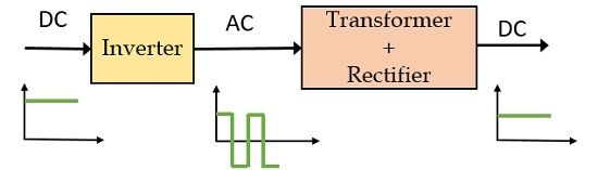
It is a two-stage conversion process as at first dc is converted into ac and then ac is changed into dc. This two-stage conversion process is less efficient and is of high cost.
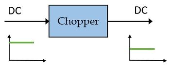
2. DC Chopper: This type of chopper circuit is considered to be static that changes fixed dc input voltage into a variable one. It behaves in a similar manner as that of an ac transformer and executes single-stage conversion in order to convert dc into dc. This conversion technique is more efficient than the one involved in ac link chopper.
Here in this content, we will discuss dc chopper circuits as these find major use in trolley cars, mine haulers, marine hoists, etc. As they possess the tremendous ability to provide speed control thus going to be used widely in electric automobiles due to their high efficiency and fast response.
The various power semiconductor devices that are used in chopper circuits are power BJT, power MOSFET, GTO, or IGTB. The representation of these devices in any circuit is generally represented by a switch with an arrow. In the open condition of the switch, no flow of current takes place. But as soon as the switch is closed, the current begins to flow in the direction of the arrowhead. The on-state voltage drop offered by these devices is around 0.5 to 0.75V. However, for operational simplicity, the drop in voltage is neglected.
Operating Principle of Chopper Circuits
The figure below represents an elementary chopper circuit:
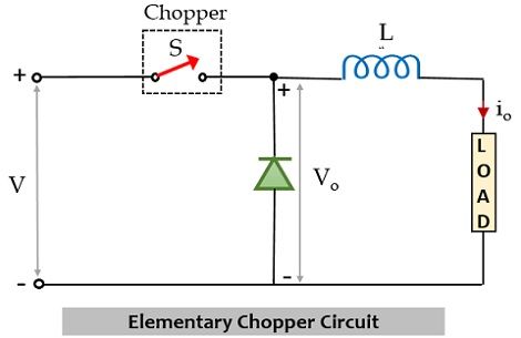
In the above figure, the switch within the box is clearly representing the chopper. Along with that, there is a freewheeling diode and an inductor connected together with a load. From the symbolic representation, it is clear that choppers act as switches, more simply these are high-speed on/off semiconductor switches. The operation of the chopper in a circuit is such that it connects and disconnects the source and load connection at a faster rate.
The circuit operation takes place in a way that a constant dc supply of magnitude V is provided at the input of the circuit. So, under the constant dc input and closed condition of the switch, the current begins to flow through the circuit and the overall source voltage appears across the load. It is to be noted here that the orientation of the diode is such that here the FD is reverse biased thus no current flows through the diode and so the load voltage is equal to V. Also, the inductor stores energy due to flowing current through it in the form of a magnetic field. This polarity of the stored energy will be opposite to the polarity with which the current is flowing according to Lenz’s Law. However, the current through the circuit will rise gradually. This represents the Ton period.
Further, when the switch gets opened this means the chopper gets off and so no flow of current takes place through the switch part of the circuit towards the load. However, in this state the charge stored within the inductor forward biases FD present in the circuit and so in this case even in a closed state flow of current takes place through the load. But this flow of current stops once the stored energy within the inductor is utilized thus it is shown below in the waveform representation that the current gradually decreases during the off state of the switch.
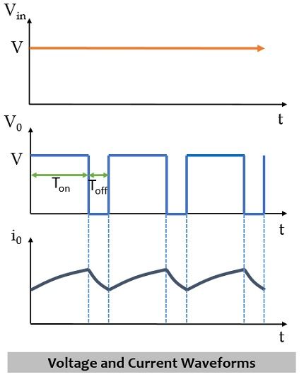
It can be clearly seen here that load voltage instantly becomes zero during the off state but the load current gradually reduces. Hence, in this way, chopper circuits provide chopped dc voltage at the load terminals.
From the above figure, it is clear that during Ton, the load current increases while during Toff the load current decreases. So, the average value of load voltage will be:
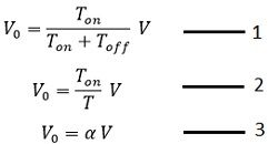
: Ton represents the on-time
Toff denotes the off-time
T represents total time or chopping period
α denotes duty cycle Ton/T
Hence, from the above equation it is clear that by varying the duty cycle, load voltage can be controlled. Also, we can analyze that load voltage is independent of load current, thus equation 2 can be modified as:
![]()
: f represents the chopping frequency
Types of Choppers
The classification of dc chopper circuits is based on the type of operation performed by the converter.
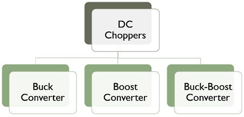
- Buck Converters (also known as Step-up Choppers)
- Boost Converters (also known as Step-down Choppers)
- Buck-Boost Converters (also known as Step-up/Step-down Choppers)
In the upcoming contents, we will discuss each type of chopper individually.
Leave a Reply