Definition: Freewheeling diode is used to protect the circuit from unusual damage caused due to abrupt reduction in the current flowing through the circuit. It is also known as Flyback diode and forms connection across the inductor to remove Flyback voltage generated across it.
Freewheeling diodes are also known as kickback diode, clamp diodes, commutating diodes, suppression diodes, or snubber diode etc.
Here in this article, we will discuss the factors responsible for the need of such diodes in switching circuits. But first, we must have the basic idea of diodes.
What is a Diode?
A diode is a semiconductor device composed of P and N-type semiconductor material. It conducts under forward biased condition when the applied potential exceeds the barrier potential. Thus acts as a closed switch.
While under reverse biased condition, the diode stops conducting and functions as an open switch.
So a Freewheeling (Flyback) diode operates in the same way that it conducts in forward biased condition but do not conducts in reverse biased condition.
- What is Flyback?
Flyback is basically defined as an abrupt increase in voltage across the inductive load when the current through the circuit shows a reduction.
Need for Freewheeling (Flyback) Diode
Consider the circuit shown below: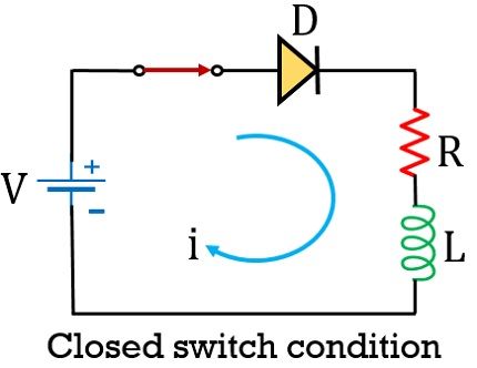
As we can see that the circuit shown above is composed of a diode, a switch and RL load. Also a supply voltage V is provided to it.
Once the switch gets closed so due to applied external potential, the diode in the circuit gets forward biased and current starts flowing through the load RL.
We know that an inductor is basically a conductive loop of wire that produces a magnetic field when current flows through it. The inductor holds the energy in the form of an electromagnetic field.
So, in closed switch condition, the flow of current through the inductor leads to the generation of the magnetic field, causing it to get fully charged.
But as the switch in the circuit gets opened as shown in the figure below: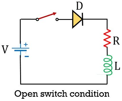
Then this will lead to an interruption in the flow of current through the circuit. Resultantly this will cause the collapsing of the earlier generated field.
And according to Lenz law, this field sets up a current in the circuit in the opposite direction, thereby leading to the production of negative potential across the inductor. This potential is known as Flyback voltage.
And this Flyback voltage across the inductor has significantly greater value than actually applied potential by the external source.
This leads to a flow of high current through the circuit. Resultantly causing a high reverse voltage to set up across the switch as well as the diode, that may lead to damaging of the devices in the circuit.
The voltage spike across the inductor is given as:
V = L di/dt
: di/dt is the rate of change of current across the inductor and
L denotes the inductance of the coil.
Thus it can be said that voltage across the inductor and current flowing through the circuit holds the relation of direct proportionality.
So, due to this reason, a free-wheeling diode is connected across the inductor to avoid the damage in the circuit.
Working of Freewheeling (Flyback) Diode
The figure below represents a circuit with a freewheeling diode:
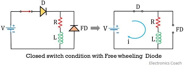 It is clear from the figure that the freewheeling diode is connected directly across the inductor. The presence of Flyback diode gives an alternate path to the current, produced due to Flyback voltage at the inductor.
Under normal operating conditions when the switch is closed, the external potential reverse biases the freewheeling diode present in the circuit. And so the freewheeling diode plays no such crucial role under normal or steady-state condition.
But in the presence of FD when the switch is opened, the voltage across the inductor forward biases the freewheeling diode.
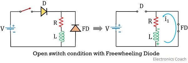 Due to small resistivity offered by FD, current in open switch condition now flows through the part of a circuit comprising of the freewheeling diode, R and L. This resultantly leads to the protection of switching device present in the circuit.
Applications of Freewheeling Diode
As we have already discussed that these diodes are used for the protection of switching devices. Thus majorly finds applications in full-wave rectifiers, relay drivers and H-bridge motor drivers etc.
Leave a Reply