Definition: Companding is a technique of achieving non-uniform quantization. It is a word formed by the combination of words compression and expanding. Companding is done in order to improve SNR of weak signals.
We know if the characteristics of the quantizer is non-linear then it causes the step size to be variable despite being constant then it is known as non-uniform quantization.
As we know in non-uniform quantization, the step size varies according to the signal level.If the signal level is low then step size will be small. So, the step size will be low for weak signal. Thus the quantization noise will also be low.
So, in order to maintain proper signal to quantization noise ratio, the step size must be variable according to the signal level.
Thus in order to achieve non-uniform quantization the process of companding is used. Let us now move further and understand the process of companding.
Model of Companding
The figure below represents the companding model in order to achieve non-uniform companding:
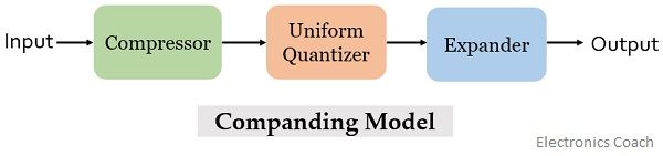
As we can see that the companding model consists of a compressor, a uniform quantizer and an expander.
We have already discussed that companding is formed by merging the compression and expanding. Initially at the transmitting end the signal is compressed and further at the receiving end the compressed signal is expanded in order to have the original signal.
Initially at the transmitting end, the signal is first provided to the compressor. The compressor unit amplifies the low value or weak signal in order to increase the signal level of the applied input signal.
While if the input signal is a high level signal or strong signal then compressor attenuates that signal before providing it to the uniform quantizer present in the model.
This is done in order to have an appropriate signal level as the input to the uniform quantizer. We know a high amplitude signal needs more bandwidth and also is more likely to distort. Similarly, some drawbacks are associated with low amplitude signal and thus there exist need for such a unit.
The operation performed by this block is known as compression thus the unit is called compressor.
The output of the compressor is provided to uniform quantizer where the quantization of the applied signal is performed.
At the receiver end, the output of the uniform quantizer is fed to the expander.
It performs the reverse of the process executed by the compressor. This unit when receives a low value signal then it attenuates it. While if a strong signal is achieved then the expander amplifies it.
This is done in order to achieve the originally transmitted signal at the output.
Characteristic of Compander
As we know companding is composed of compression and expanding. So, here in this session we will separately discuss the compressor and expander characteristic.
Compressor characteristic: The figure below shows the graphical representation of characteristic of the compressor:
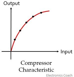
The graph clearly represents that the compressor provides high gain to weak signal and low gain to high input signal.
Expander characteristic: Here the figure shows the characteristic of expander:
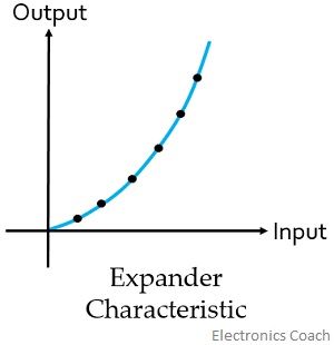
As we have already discussed that expander performs reverse operation of the compander. So, it is clear from the above figure that artificially boosted signals is attenuated to have the originally transmitted signal.
The figure below represents the companding curve for PCM system: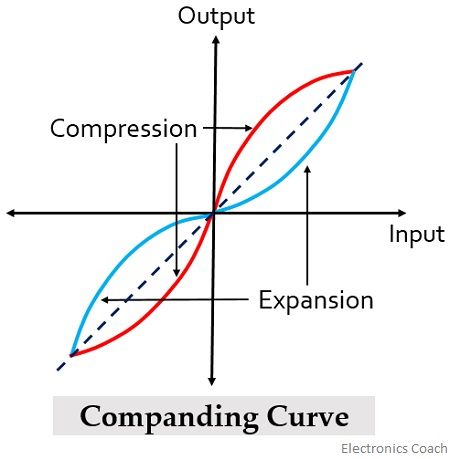
The compressor and expander performs inverse operations thus in the above figure the dotted line represents the linear characteristic of the compander indicating that the originally transmitted signal is recovered at the receiver.
Sanjana says
This explanation is very good. Thankyou
Mohit says
Thanku for this content. It is very helpful.
Suyash Sudhir Sumant says
Thank you for explaining in such simple words.