Definition: The instruments that are used to express the measuring quantity in numeric format is known as Digital Instruments. A digitized information is somewhat easy to be handled and transmitted thus widely preferred nowadays.
Quantization is the basis of working of a digital instrument. It is an act of transforming an analog signal into its digital form. Digital instruments are composed of logic circuits that carry out measurement of the quantities.
Due to several advantages of digital instruments such as high speed, errorless results, better resolution and greater accuracy over analog instruments, the popularity of digital instruments are increasing rapidly.
Block diagram of digital instrumentation system
The figure below shows the block diagram of the digital instrumentation system:
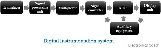
As we can see, it consists of various units, the operation of each is discussed below:
- Transducer: A transducer is a device that changes the physical quantity to be measured into its equivalent electrical form. The applied input can be temperature, pressure, velocity, displacement etc. It basically converts a form of energy into another.
- Signal processing unit: This unit is mainly composed of amplification circuitry along with balancing circuits and calibrating elements. The output of the transducer which is the electrical form of the quantity to be measured is fed to the signal processing unit.This basically amplifies or modifies the output of the transducer to such an extent that it can be easily detected and accepted by the other units of the system.
- Multiplexer: Multiplexer mixes the multiple analog signals supplied by the processing unit. It produces an individual signal by muxing various applied signals. This signal is then processed further.
- Signal converter: This unit takes the output of the multiplexer and generates such a signal that can be processed by further units of the system.
- Analog to digital converter: ADC plays a crucial role in the digital instrumentation system. It converts the applied analog data signal into its equivalent digital form. This converted digital data is then provided to the display unit.
- Display unit: This unit shows the actual quantity that is to be measured in the numerical form. This can be a CRO or a computer monitor etc. depending on the need of the user.
- Auxiliary Equipment: This unit is responsible for the functioning of the overall system. It basically helps to have linear results and performs tasks like a limit comparison to ensure proper working of the system.
Basic Digital instruments
A digital voltmeter is a device that measures voltage and displays the quantity directly in a digital manner rather than analog representation. Here, the measured voltage is provided in the form of discrete numerals. It is abbreviated as DVM.
Due to its versatility and accuracy, it is widely used in various ac and dc voltage measuring applications.
- Digital multimeter:
A digital multimeter helps us to measure voltage, current and resistance in a digital manner. Or we can say, that a digital multimeter is a type of digital instrument that generates a digitized value of voltage, current or resistance. DMM is the acronym for digital multimeter.
As digital instruments are said to be highly accurate but it is noteworthy in their case that the level of accuracy somewhat depends on the analog to digital converter employed in the system.
A key factor that differentiates the digital voltmeter from the analog one, is the high input impedance offered by it along with small instrument size.
- Digital frequency meter:
It is a type of digital instrument that measures the frequency of the applied periodic signal. It consists of an attenuator, wave-shaping circuit along with logic gates, counters and flip-flops in order to measure the frequency of the electrical signal.
Digital frequency meter measures the signal frequency by converting it into a train of pulses. In other words, a combination of pulses is the applied input to the system. Here, each cycle of the signal to be measured represents one pulse.
The pulses that occur on definite time duration is then counted. This count shows the frequency of the applied input signal. The pulse count is done through an electronic counter having high speed. Due to this, signals having high frequency can also be measured.
Advantages of Digital Instruments
- By using the digital instrument, one can have a highly accurate measurement which is not achieved in the case of an analog system.
- Digital instruments due to their numeric data representation format provide better readability than analog instruments.
- Energy consumption in the case of digital instruments is very less.
Disadvantages of Digital Instrument
- High cost and does not support easily potable characteristic.
- These get easily affected by the noise or other external factors.
- These are highly susceptible to variation in temperature and humidity.
Jahan says
Usefull and easy to understand content! Thanks