Definition: Current Commutated Chopper also known as Resonant-Pulse Commutated Chopper is a type of chopper that allows the thyristor to get commutated by the use of an oscillatory circuit.
It is known to be a reliable commutation technique.
Introduction
We all have the basic idea that choppers are circuits that possess turn-on and turn-off mechanisms. Commutation corresponds to turning the thyristor off. Previously, we have seen that commutation can be of two types:
1. Forced Commutation: In this technique, external elements such as L and C are used to turn off a conducting thyristor. It can be sub-classified as:
- Voltage Commutation
- Current Commutation
2. Load Commutation: In this technique, a conducting thyristor is brought to a non-conducting state if the load current becomes zero either because of the nature of load circuit parameters or the current is transferred from conducting thyristor to another device.
One of the important characteristics possessed by current commutation is that the diode is connected in antiparallel arrangement with the main thyristor that leads to reverse biasing of the main thyristor due to the drop across the diode.
It is to be noted here that the voltage drop is nearly 1 volt thus current commutation is a quiet flow than the voltage commutation.
Circuit of Current Commutated Chopper
The figure down below represents the circuit diagram of the current commutated chopper:
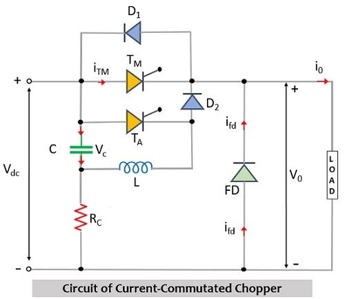
Here TM is the denotation for the main thyristor while TA represents auxiliary thyristor. D1 and D2 are two diodes along with inductor L and capacitor C. Also, there is a freewheeling diode represented by FD and a charging resistor Rc.
Similar to the voltage-commutated chopper which we have discussed recently the circuit operation considerations are as follows:
- The value of the charging resistor must be high.
- The current flowing through the load will be of invariable nature.
- The thyristors and diodes must show ideal behavior.
Here in the above circuit ic is the commutating current, iTM is the current through the main thyristor, while iFD is the current through the freewheeling diode and io represents the load current. The operation of this circuit is somewhat similar to the voltage-commutated circuit in the sense that the energy required to commutate the circuit is provided by the capacitor.
Also, the capacitor is charged through input voltage Vdc. Also, when TM is in conducting state, the commutating circuit will be in an inactive state. The commutation process begins when TA is turned on.
Working of Current-Commutated Chopper
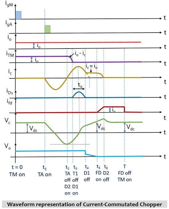
Consider the circuit shown above. The circuit operation begins with the charging of the capacitor up to the peak of the supply input and the path through which charging of the capacitor takes place will be +Vdc – C – Rc – (-Vdc). Initially, the main thyristor TM is triggered at t = t0, and at this time, TM will be in the conducting state. This allows the current to pass through the main thyristor and appears at the load. Hence V0 = Vdc.
Now let us see how the process of commutation takes place.
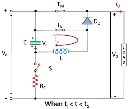
So, at instant t = t1, in order to commutate TM, the auxiliary thyristor i.e., TA is triggered. As soon as TA is triggered, it comes into conducting state then oscillatory current ic begins to flow through the components +C – TA – L – (-C) of the circuit. Further, at the instant t2, the current through the capacitor will get reversed but will be maximal. Hence, at t2, Vc = -Vdc. Due to the negative polarity across the capacitor, TA will get reversed biased hence will be commutated while TM will be unaffected and so in this case the current through the load will be i0 while V0 = Vdc.
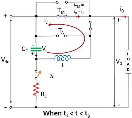
Now, as TA is turned off and TM is still in the conducting state at instant t2, the oscillatory current ic will flow through +C – L – D2 – TM. This means that the oscillating current will flow through the main thyristor this time and not through D1. Here, in this case, the direction of flow of ic will be opposite to that of the previous direction and so there will be a decrease in the current flowing through the main thyristor i.e., iTM. The direction of flow of oscillating current is reverse to the flow of load current i0 through TM therefore, iTM = I0 – IC.
At instant t3, the oscillating current ic will reach i0, and therefore, iTM = 0, this leads to turning off of the main thyristor at t3. From the above explanation, it is clear that oscillatory current turns off TM thus it is referred to as a current-commutated chopper. And the voltage across the load will be Vdc. At this instant, TM gets turned off and ic exceeds i0, hence after instant t3, the load current is supplied by ic. While the excess current ic – i0 will flow through diode D1 and due to the drop across D1, TM will be reverse biased between the instant t4-t3 (i.e., tq). At time instant t4, if the value of Vc becomes more than the supply input Vdc then this forward biases the freewheeling diode.
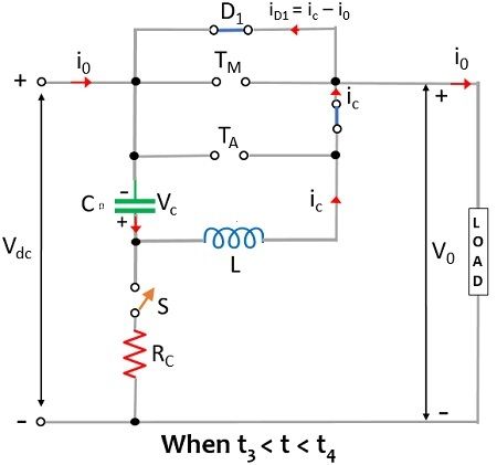
Furthermore, at t4, ic becomes equivalent to i0, and therefore the current through D1 will become 0 thereby turning off diode D1. However, at the same time, a constant current from Vdc to the capacitor to the inductor to diode D2 and lastly to the load will flow. This charges the capacitor linearly and at instant t5 the capacitor will get charged to source voltage. However, during t5 – t4 the current through the capacitor will be i0. At t4, D1 is in an off state therefore VTM = VTA = Vc and so the load voltage V0 will Vs – Vc.
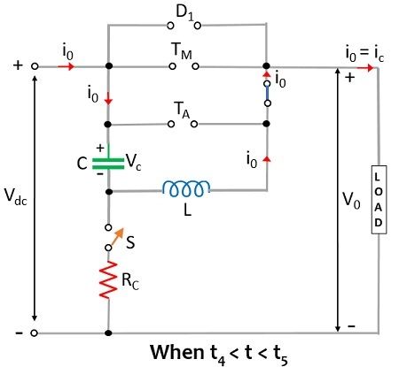
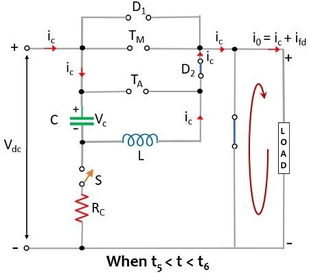
However, at t5, Vc = Vs, and as V0 = Vs – Vc therefore, the load voltage will be 0 at this instant. At this instant, overcharging of capacitor above the supply input takes place, and this forward biases the freewheeling diode and it starts conduction. This allows the flow of load current i0 through FD.
At this particular instant, the commutating current ic is non-zero and as C forms the connection through the load i.e., +Vdc – C – L – D2, and overcharging takes place as energy from the inductor is transferred to the capacitor. However, at t6, ic becomes 0, and the voltage across the capacitor exceeds the source voltage. In between t5 to t6, the load current i0 will be the sum of commutating current (ic) and current through FD (ifd). When ifd increases, then this leads to decaying of ic hence resultantly ic will be 0 therefore ifd = i0. Thus, this commutates the circuit and the overall turn off time will be t6 – t1.
The waveform representation for the same is shown below:
Advantages
- The auxiliary thyristor TA will undergo natural commutation.
- It is a reliable commutation technique till the load current is smaller than the peak commutation current.
- The capacitor is in always charged state.
This is all about the current commutated chopper.
Leave a Reply