Definition: Voltage-Commutated Chopper or Jones Chopper is a chopper circuit that commutates the thyristor by the application of a large reverse voltage across the thyristor. It is one of the earliest and simplest chopper circuits and is mainly used in high power circuits where load fluctuation is not a major concern.
It is sometimes called parallel-capacitor turn-off chopper, or impulse commutated chopper. It is known to be an example of class D commutation of the thyristor.
Introduction
We have discussed in previous content that a chopper is a power semiconductor device with circuitry that exhibits turn-on and turn-off mechanisms. To represent the whole circuit arrangement of the chopper, a switch inside a dotted rectangular box is used. We know that a chopper is a static device that changes fixed dc voltage into adjustable dc voltage and is known to be such a switch that allows power flow within a circuit for a specific duration.
The word ‘commutation’ defines the process of turning off a thyristor that is in conducting state. In the case of dc circuits, the need for separate commutation circuitry is quite essential so as to turn off the main power thyristor. We can recall that a thyristor in conducting state can be turned off by decreasing the value of anode current below the holding current and by applying a reverse voltage across the thyristor so as to enable its forward blocking mode.
Mainly the ways in which commutation is achieved is of the following types:
1. Forced Commutation: In this technique, external elements such as inductor and capacitor are used to turn the thyristor off as these elements do not carry load current on a continuous basis. It can be of two types namely:
- Voltage Commutation
- Current Commutation
2. Load Commutation: The thyristor in conducting state, stops conduction when the value of load current either reaches zero because of the natured possessed by the load circuit parameters or it is transferred to any other device to bring the thyristor to the off state.
Basically, in voltage commutation, a large conducting thyristor is turned off by the application of large reverse voltage. This reverse voltage across the conducting thyristor reduces the anode current and rapidly it will reach zero. Also, the reverse voltage existing across the thyristor will keep it in the off state. Hence, the further flow of current through the circuit is prevented.
Circuit of Voltage Commutated Chopper
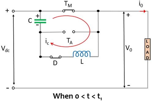
The figure given below shows the circuit representation of voltage commutated chopper:
 Here thyristor TM is the denotation for the main thyristor while TA is for the auxiliary thyristor, C is the capacitor, D is the diode and the load in the circuit is a combination of resistor, inductor, and capacitor. Here FD represents a freewheeling diode in order to protect the circuit against inductive load.
It is to be noted here that for the operation of the chopper to take place, it is mandatory that the capacitor is charged up to the supply input with a similar polarity i.e., shown above. So, in order to charge the capacitor in the circuit there are two methods:
- First, switch S is closed so that the capacitor will get charged through the supply input voltage Vdc and the charging current will flow through the path Vdc – C – S – Rc – Vdc.
- Second, TA in the circuit is triggered so the capacitor will be charged and the charging current will flow through Vdc – C – TA – RLE – Vdc. Once TA gets off then the charging current decays and attains zero value.
Once the capacitor is charged with supply input and given polarity the chopper can begin its operation. Some necessary assumptions relative to the chopper circuit are as follows:
- The load current is of invariable nature.
- Ideal thyristors and diodes are considered over here.
Let us now proceed to understand how the circuit operation takes place.
Working of Voltage Commutated Chopper
Consider the circuit representation shown above where the capacitor is already charged with the peak of the supply input.
Initially, TM i.e., the main thyristor is triggered then in the conducting state of the device the supply input will appear across the load, thus, V0 = Vdc. In this case, two currents flow through two sections of the circuit, one is the load current io while the other is the commutation current ic. The current starting from Vdc flows through TM then reaches load is the load current io. While the other current flows in the oscillatory circuit that is constituted by capacitor C, thyristor TM, inductor L, and diode D.

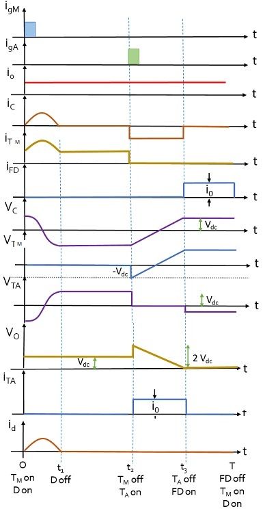
It is to be noted here that ic rises from 0 to maximum value in the duration between when the capacitor voltage is equivalent to the supply input and the voltage across capacitor becomes zero, respectively. And this occurs at t1/2 of the time period. However, when ic starts decreasing from the maximum value to 0, the capacitor begins to charge again but this time with the reverse polarity of the supply input i.e., – Vs. This will take place at the instant t1. The diode D in the circuit keeps the voltage – Vs constant. However, during the half-cycle, the overall current through the main SCR TM is the sum of capacitor current and the load current.

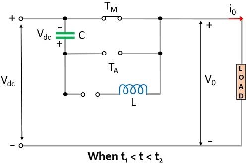
Further, the auxiliary thyristor TA is triggered, however, due to the existing polarity across the capacitor, the thyristor TM gets reverse biased and it comes into the non-conducting state, thus, it gets off. As the voltage across the capacitor is responsible for turning TM off thus it is regarded as a voltage commutated chopper. Due to this, the current iTM becomes equal to 0 and further, through capacitor and TA there will be a path for the flow of load current. In this case, i0 will flow through Vdc – C – TA – Load – Vdc.

Hence at this time, the load voltage will be the sum of applied dc input voltage and the voltage across the capacitor. Therefore, the load voltage at t2 instant will be given as V0 = Vdc + Vdc = 2 Vdc. Once the capacitor begins to discharge through the load, the voltage across the capacitor decreases, Vc = VTA = 0. Due to this, the load voltage V0 changes from 2 Vdc to Vdc.
However, the charging of the capacitor takes place again with the polarity of the supply input and once the capacitor gets fully charged then it makes the auxiliary thyristor reverse biased. Hence no conduction will take place through it. Thus, at this time, Vc = VT1 = Vs and V0 = 0.
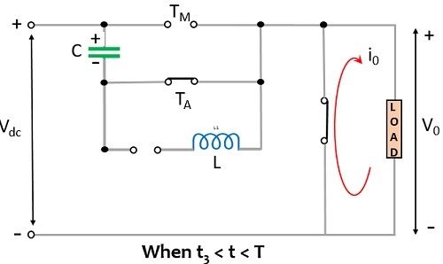
When the capacitor gets overcharged slightly, the FD in the circuit gets forward biased, this is clearly shown in the figure below:

After a certain point of time, the main thyristor TM is triggered and the whole operation takes place again. The figure down below shows the current and voltage waveforms for voltage commutated chopper:

Due to the simplicity possessed by the voltage commutated chopper, it finds a huge range of applications.
Leave a Reply