Definition: Demultiplexer performs the reverse operation of the multiplexer i.e. it takes a single output and can guide that single output through many outputs. The output to which the input signal is to be passed is decided by the control logic. The control logic can be manipulated by changing the value of the control signal.
Thus, it is termed as the demultiplexer as it takes one input and generates several outputs.
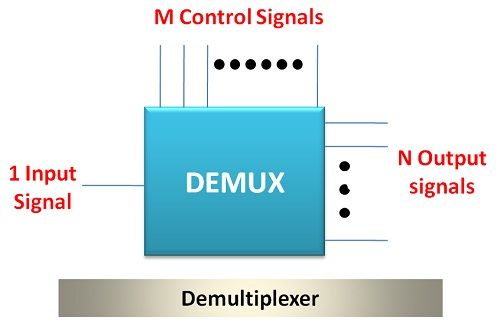
There can be various types of demultiplexer circuits depending on the number of output. The input will be always one in number.
The demultiplexer can be digital as well as analogue depending on the type of input and output. In this article, we will discuss digital demultiplexer which is significant in the present era. You must be thinking that what is the need of demultiplexer?
The multiplexer converts parallel data such as audio, video etc. into serial data by transmitting it through a single data transmission line. But on the receiver side, we need parallel data. To retrieve the parallel data from the serial data we need demultiplexer.
The utilities of demultiplexer do not end here. It is a significant digital circuit. Consider a situation when you have a single source and you need to serve it to multiple users, in this case, we need demultiplexer. Thus, demultiplexers play a crucial role in the communication system.
If the output of the demultiplexer is 4 it can be termed as 1:4 Demux. And if the outputs are 8 in number it can be termed as 1:8 users. Thus, depending on the number of the outputs the demultiplexer is termed. Let’s discuss 1:4 demux in detail.
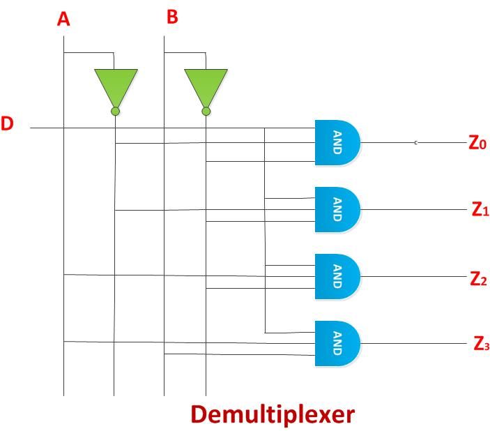
1:4 Demultiplexer
The 1:4 Demultiplexer consists of 1 input signal, 2 control signals and 4 output signals. The number of the output signal is always decided by the number of the control signal and vice versa.
We have already studied the equation in our previous article of Multiplexer.
There are 1 NOT gates through which control signals are passed, and 4 AND gates, which decides or control the output. The combination of the input signal along with control signals will decide that the output through which input signal will pass through.
| Inputs | Outputs | |||||
|---|---|---|---|---|---|---|
| A | B | D | Z0 | Z1 | Z2 | Z3 |
| 0 | 0 | 0 | 0 | 0 | 0 | 0 |
| 0 | 0 | 1 | 1 | 0 | 0 | 0 |
| 0 | 1 | 0 | 0 | 0 | 0 | 0 |
| 0 | 1 | 1 | 0 | 1 | 0 | 0 |
| 1 | 0 | 0 | 0 | 0 | 0 | 0 |
| 1 | 0 | 1 | 0 | 0 | 1 | 0 |
| 1 | 1 | 0 | 0 | 0 | 0 | 0 |
| 1 | 1 | 1 | 0 | 0 | 0 | 1 |
The above truth table determines the possible combination of input signal and control signals. For every combination of control signals, there can be two input values i.e. 0 and 1. For example, if both the control inputs are 0 then it will generate two possible combinations, one with 0 and another with 1. Thus, in this way, the total possible combination will be 8.
Every possible combination determines that the input will pass through a particular output terminal.
Applications of Demultiplexer
- Communication System: Demultiplexers play a crucial role in the data transmission process. In the conversion of parallel data to serial, demultiplexers are used. Besides, in various communication circuits, demultiplexers are used for providing a single source to multiple users.
- Arithmetic logic Unit in Computers: Demultiplexers are used in ALU of the computer system, in which the output of the ALU is fed as an input to the demultiplexers and the output of the demultiplexers is then fed as input to various registers which store the results processed by ALU.
- Serial to parallel Converter: The parallel data which is converted into serial data at transmission side by multiplexers is converted back into parallel data by demultiplexer at the receiver side.
For various application in communication and electronics realm, we need multiplexers as well demultiplexers, both works in synchronization to achieve a particular task. We can extend the outputs by increasing the output terminals of demultiplexer but then the control signal should also be varied.
Leave a Reply