The main difference between demultiplexer and decoder is that a demultiplexer is a combinational circuit which accepts only one input and directs it into one of the several outputs. On the contrary, the decoder is a combinational circuit which can accept many inputs and generate the decoded output.
The demultiplexer has selection lines to allow the input to follow one of the selected paths for generating it at the output. The decoder does not possess any selection lines as it has nothing to do with the selection of the path.
Another crucial difference between demultiplexer and decoder is that the demultiplexer accepts the data bits while the decoder does not accept data input. The control signals applied to the decoder acts as the input terminals of the decoder.
We will put light on some more crucial differences between demultiplexer and decoder with the help of comparison chart. But before embarking on it let’s have a look at the roadmap of this article.
Contents: Demultiplexer and Decoder
| Parameters | Demultiplexer | Decoder |
|---|---|---|
| Definition | A demultiplexer is a circuit which takes only one input and switches it to one of the several outputs with the help of selection lines. | A decoder is the circuit which decodes the input signal fed to it with the help of control signal. |
| Data Input | A demultiplexer accepts the data as input. | A decoder accepts control signals as input. |
| Number of Inputs | Only one | One or more signals can be given as input. |
| Number of Outputs | The output depends on the number of selection lines. The number of outputs will be equivalent to 2 raised to the power of selection lines. If there are n selection lines then output will be 2^n. | The outputs depends on the number of control signals. If there are n control signals then the output will be 2^n. |
| Need of selection lines | Required | Not required, but control signals and enable signal is required. |
| Main Function | Used for switching | Used for decoding of the encoded input terminal. |
Definition
Demultiplexer
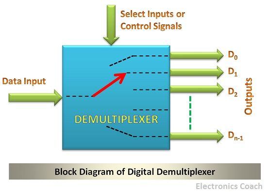
A demultiplexer is exactly opposite in functioning than the multiplexer. A multiplexer takes many inputs and generates a single output while a demultiplexer takes the single input and generates several outputs. To decide which output path is to be allocated for the representation of the signal there are selection lines.

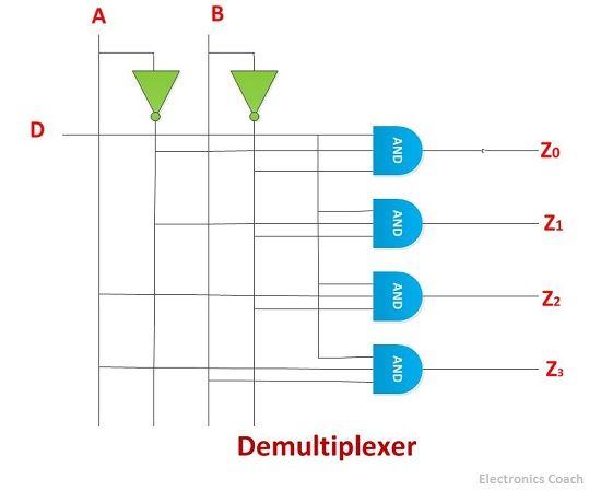
The combination of signals from selection lines selects one of the several outputs and then the input is switched to that path. To understand it clearly, let’s consider a demultiplexer circuit. The below diagram depicts the connection diagram of demultiplexer circuit. This is the example of 2:4 demultiplexer.

There are four output terminals. Therefore, there must be 2 selection lines. The combination of the signals from 2 selection lines will select one by one all the four outputs and thus, the input will be redirected to that switching path.
The data signal is represented by D. This is the main data which is to be transmitted through the switching network, i.e. demultiplexer. Now, to understand how does it work we need a careful observation of the truth table.
| Inputs | Outputs | |||||
|---|---|---|---|---|---|---|
| A | B | D | Z0 | Z1 | Z2 | Z3 |
| 0 | 0 | 0 | 0 | 0 | 0 | 0 |
| 0 | 0 | 1 | 1 | 0 | 0 | 0 |
| 0 | 1 | 0 | 0 | 0 | 0 | 0 |
| 0 | 1 | 1 | 0 | 1 | 0 | 0 |
| 1 | 0 | 0 | 0 | 0 | 0 | 0 |
| 1 | 0 | 1 | 0 | 0 | 1 | 0 |
| 1 | 1 | 0 | 0 | 0 | 0 | 0 |
| 1 | 1 | 1 | 0 | 0 | 0 | 1 |
It is evident from the truth table that there can be two possibilities for the data signal. It can be either 0 or 1. For each possibility of the data signal, there can be four possible combinations of the selection line. Let us discuss that in detail.
Case 1: When the selection lines A and B both are 0
If data terminal D is 0, then, in this case, the output terminal which is to be selected will be Z0. But no data will be transmitted as there is no data signal which is indicated by its 0 value.
If data terminal is 1, then this output will be redirected to the path Z0.
Case 2: When the selection line A is 0 and B is 1
If data terminal D is 0, then the output terminal which is to be selected will be Z1, but since the value of signal D is 0, thus no output will appear.
If the value of data signal D is 1, then this output 1 will be reflected at the output terminal Z1.
Case 3: When the selection line A is 1 and B is 0
The output terminal selection, in this case, will be Z2, if the data signal D is 0, then 0 will be reflected at the output end Z2, and if data signal D is 1, then 1 will be reflected at the output terminal Z2.
Case 4: When the selection line A and B both are 1.
The output terminal selected will be Z3, if the data terminal D is 0, then it will be redirected as it is through the output terminal Z3. On the contrary, if the data terminal D is 1 then this signal will be redirected as it is through the output terminal Z3.
Decoder
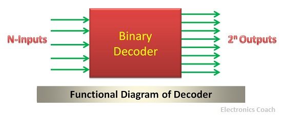
The decoder as its name suggests “DE” and “CODER”, it decodes the encodes signal which is given to it as input. The signal to be decoded is given to it as the control signal.

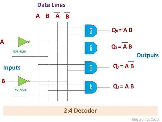
The output signals present in the decoder set to high when the desired combination of control signal occurs. You will understand more clearly with the help of it connection diagram.

It is clear from the connection diagram of 2:4 decoder that, it consists of 4 AND gates. Out of these 4 AND gates, only one will be high at a particular time; the other will be zero. There are two inputs A and B, which acts as control inputs for the decoder circuit. Many decoder circuits are designed with an enable signal which is set to high when the decoder performs its operation.
| Inputs | Outputs | ||||
|---|---|---|---|---|---|
| A | B | Z0 | Z1 | Z2 | Z3 |
| 0 | 0 | 1 | 0 | 0 | 0 |
| 0 | 1 | 0 | 1 | 0 | 0 |
| 1 | 0 | 0 | 0 | 1 | 0 |
| 1 | 1 | 0 | 0 | 0 | 1 |
The truth table of the decoder is given below. It is clear from the truth table that the combination of the control signals decides which input is set to be high.
Key Differences Demultiplexer and Decoder
- The demultiplexer is basically a switching element which switched the input signal from one output path to other. The decoder is the circuit which decodes the signal from one particular format to the another desired format.
- The demultiplexer and decoder may resemble each other, but if you observe carefully, you can understand the difference very clearly. In demultiplexer, the combination of the selections lines decides the output terminal to be selected, in decoder the combination of the data input lines decides the output terminal to be selected.
- Another key difference between demultiplexer and decoder is that a demultiplexer accepts only single input while a decoder can accept several inputs.
- The demultiplexer and decoder are different in functioning; the former acts switch while the latter performs the complete different action of decoding.
Conclusion
The demultiplexer and decoder both are the combinational circuit, but both are different in terms of not only in functioning but also in designing architecture. The presence of selection lines in demultiplexer also differentiates it from decoder circuit.
Leave a Reply