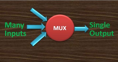
Definition: Multiplexer is a combinational logic circuit which allows only one input at a particular time to generate the output. The signals which control which input will be reflected at the output end is determined by the SELECT INPUT lines. A multiplexer is often written as MUX in the abbreviated form. It is also called as Many-to-One circuit. This is because of its ability to select one signal out of many inputs.
The MUX is a very crucial component of the communication system. This is because, in such systems, we need to select a single channel from various other channels.
A multiplexer can be considered as a digitally controlled switch. The controlling code which selects a particular input line can be given as binary input in the form of selection line. The output will be one of the inputs given to MUX, which is decided by selection lines.

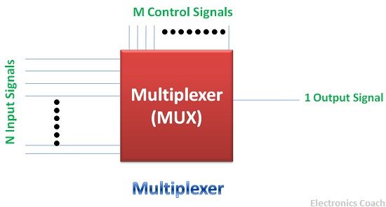
The Circuit of the MUX along with input and output terminals can be understood with the help of the below diagram.

A multiplexer can take any number of inputs line but then the selection line will be according to the number of inputs. The relation between the selection lines and the input lines is given in the equation below.

A multiplexer can be designed with various inputs according to our needs. If we have four inputs and we want to select a single one then we can use four-to-one (4:1) MUX. If we have 8 inputs we can design a multiplexer with 8 input lines, but the selection line should be in accordance with the above-mentioned equation.
In this article, we will discuss the designing of 4:1 MUX with the help of its circuit diagram, input line selection diagram and truth table.
Four-to-One Multiplexer
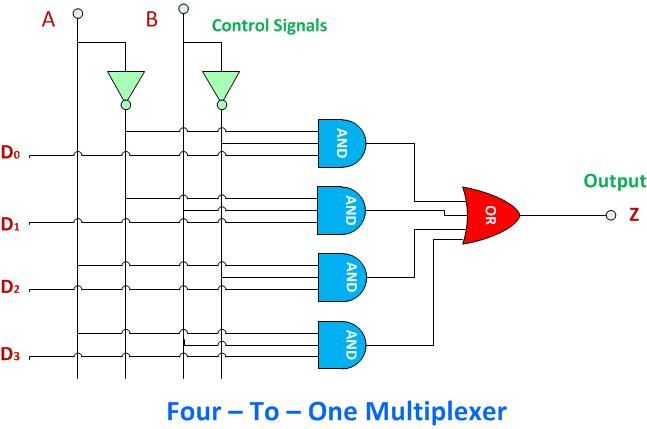
In 4:1 MUX, there will be 4 input lines and 1 output line. And to control which input should be selected out of these 4, we need 2 selection lines.
Thus, it is evident from the diagram below that D0, D1, D2 and D3 are the input lines and A, B are the two selection lines. The combination of binary numbers given as a selection line will determine the output of the MUX.

Now, there will be 4 cases as described below:-
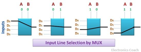
Case 1: When the selection line A represents 0 and selection line B also represents 0 then the input line which will be selected to pass from multiplexer will be D0. Thus, MUX will be a short circuit for input line D0 and will be open circuited for other input lines.
Case 2: When the selection line A represents 0 while selection line B represents 1, then the input line which will be selected will be D1. In this case, MUX will behave as a short circuit for input line D1 while it will behave as an open circuit for other input lines.
Case 3: When the selection line A is 1 and B is 0 then the input line D2 will be generated at the output. In this scenario, the MUX will allow only D2 to pass through it and other input will be blocked.
Case 4: When both the selection line represents 1, then the last input line will be selected i.e. D3. In this case, the MUX will allow the only D3 to pass through it and other input lines get blocked from passing through MUX.
Truth table
| Data Select Inputs | Input Selected | Input | Output | |
|---|---|---|---|---|
| A | B | D | D | Z |
| 0 | 0 | D0 | 0 1 | 0 1 |
| 0 | 1 | D1 | 0 1 | 0 1 |
| 1 | 0 | D2 | 0 1 | 0 1 |
| 1 | 1 | D3 | 0 1 | 0 1 |
On the basis of the truth table of the 4:1 MUX we can write the equation of the multiplexer. The equation of the 4:1 MUX is described in the diagram below.

Input Line Selection by MUX
The input line selection is done by selection lines. We have already discussed the possible cases of combination of binary values which gives the desired input line as output. We can also understand this with the help of the input line selection diagram described below.

In the above diagram, the Multiplexers are defined for each case. For every combination of the selection line, one input is selected.
Application of Multiplexers
Multiplexer is a crucial combinational circuit which is used in various significant application. Multiplexers can select data input lines as per our requirement. This is the reason multiplexers are often termed as “Data Selectors”. These find application in various realms of digital and as well as analogue electronics.
Some of the significant applications are described below:-
- Parallel Data Transmission: If we transmit the “n” parallel data bits then we need “n” parallel data lines. Unfortunately, this is a cumbersome process. We can ease the way by utilizing Multiplexer. It can transfer the parallel data using a single wire at the transmission side. And converting these serial bits into parallel at receiver with the help of demultiplexer.
- Data Routing: Multiplexer is a good alternative for data routing in a desired path. With the help of selection line of the multiplexer, we can control the flow of input data from a particular path.
Advantages of Multiplexer
Multiplexer can facilitate the transmission of data through a single line, this makes the transmission circuit economical and less complex. Besides, the ability of multiplexer to switch digital signals can be extended to switch video signal, analogue signals etc.
The best thing about analogue switching by multiplexer is that the analogue switching current assumes an extremely low value in the range of 10mA-20mA. Due to such a low magnitude of the current, the heat dissipation is very low.
Mike White says
Hello, its impressive article and fully explained, keep it up all the time.