Definition: Digital Storage Oscilloscope is an instrument that analyses the signal digitally and stores the data in the electronic digital memory. By examining the stored traces in memory, it can display visual as well as numerical values.
It digitizes the input signal in order to have subsequent digital signals. The input is stored in digital memory in the form of 0 and 1. This stored digitized signal is then viewed on the CRT screen after the signal reconstruction in analog form.
Here, the digital copy of input waveform is stored and further analysed using Digital Signal Processing techniques. The maximum frequency that can be measured by using Digital Oscilloscope basically depends on sampling rate and nature of converter.
Sometimes people misconstrue in between digital voltmeter and digital storage oscilloscope.
A digital voltmeter records fluctuation in voltage. On contrary, Digital oscilloscope displays a graphical representation of the signal. It also helps to determine unexpected voltage source.
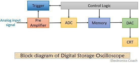
Block Diagram of Digital Storage Oscilloscope
The figure below shows the block diagram of the digital storage oscilloscope-
Here, the CRT employed in the circuit displays the data stored in the electronic digital memory.
As the data in memory is stored in digital form, the signal is reconstructed in analog form in order to be displayed on the screen of CRT.
Working Of Digital Storage Oscilloscope
From the figure shown above, we can see that an analog input signal is fed into the pre-amplifier unit. This unit amplifies the input so as to raise the level of the amplitude of the signal.
This signal is then fed to an analog to digital converter (ADC) and the trigger detector. As the voltage crosses the threshold value, the device starts recording on the application of the signal sent by the trigger unit.
The output of the pre-amplifier is sampled by the ADC at regular intervals. The digital output provided by the ADC is stored in memory at consecutive locations. The recording of signal continues until the memory is full.
The DAC employed in the circuit produces analog signal to be displayed in CRT.
Any further changes in the applied input, re-triggers the oscilloscope which causes the memory to reset. That means the memory is overwritten with the new upcoming data unless the system is in HOLD mode.
By the application of HOLD mode, the signal traces can be analysed by the user according to the user’s choice.
The size of the memory unit determines the number of samples stored in it. One can alter the length of recording by changing the sampling frequency of ADC.
In the case of the digital oscilloscope, many different input channels are used. But, the memory available to each channel gets reduced. When all the channels share a common store. This is done through multiplexing.
Here, 40 channels oscillator are obtainable commercially having storage capability of 25000 dots. Many oscillators employ floppy disc storage capability.
At the time of digitization in order to make sure that no information is lost, according to Sampling Theory, the sampling rate must be twice as fast as the highest frequency of input signal. Failing of which will give rise to aliasing effect.
Waveform Reconstruction
Although the input is sampled according to sampling theory, aliasing effect can still occur. This is so because the output is present as series of dots, that corresponds to the sampled value.
Digital storage oscilloscope uses interpolation technique, for visualization of final waves.
Interpolation is a technique that creates new data points with the help of a discrete set of known data points. It is basically of two types-
- Linear interpolation
- Sinusoidal interpolation
Let’s have a look at the figure illustrating interpolation methods-
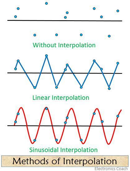
In linear interpolation, the dots are connected together by a straight line. It can be used in pulsed or square wave generation but not in case of sinusoidal waves.
On contrary, in sinusoidal interpolation, the dots are connected so as to form sinusoidal waveform. But it is not suitable for square or pulse waves.
Sampling technique gives rise to another problem when used in digital oscilloscopes. The transient or glitches that exist in between the sample points can be missed out.
The problem is solved by envelope mode oscilloscopes can be used. It employs special logic circuitry due to which the sample and digitizing circuitry run at high speed. The functioning of which is independent of the setting of display time.
In this, each sample value is compared with the previous one and resultantly the higher one is stored in memory.
Advantages
- They possess infinite storage time.
- It can be easily operated.
- Digital storage oscilloscope allows flexible display property.
Applications
- It is used in audio and video recording.
- It is used in radio broadcasting for signal testing.
- In circuit debugging, it is used for testing of the voltage of the signal.
In case of digital storage oscilloscope, the replacement of internal equipment is more economical. This is so because it employs CRT which is cheaper than analog storage oscilloscope.
Leave a Reply