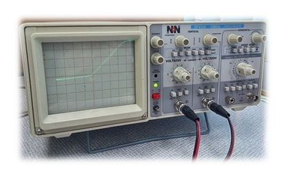
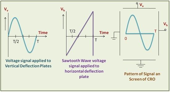
Definition: The cathode ray oscilloscope is the instrument which generates the waveform of any electrical quantity. The waveform is generated in such a way that the amplitude of the signal is represented along Y-axis and the variation in the time is represented along X-axis.
CRO is the measuring device as well as it can generate waveforms in terms of amplitude and time because it is very easy to measure the amplitude of the voltage signal to determine its intensity.
The non-electrical quantities can also be measured with the help of Oscilloscope, but we need to convert it in electrical form before applying it to input terminals of Oscilloscope because only electrical quantities can be given as an input to the Oscilloscope.

Cathode ray Oscilloscope is considered to be the heart of electronics instrumentation. This is because in the realm of instrumentation we deal with measurement of physical quantities such as pressure, temperature, displacement. But their physical appearance does not provide a single basis to measure such quantities.
Fortunately, the invent of transducers has alleviated this problem, as with the help of it any physical quantity can be converted into an electrical quantity. These electrical quantities are expressed in terms of voltage and current which can be easily measured with the help of oscilloscope.
For waveshaping applications, an oscilloscope is considered very significant as any kind of waveforms can be generated with the help of Oscilloscope.
Block Diagram of Oscilloscope
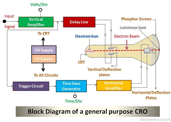
The functionality of Oscilloscope can be interpreted more easily with the help of its block diagram. To understand the block diagram more clearly we need to focus on its major parts. Let’s discuss what are those parts which made up a device which can generate the waveform.

Parts of Oscilloscope
- Cathode Ray Tube
- Vertical Deflection System
- Horizontal Deflection System
- Delay line Circuit
- Trigger Circuit
Let’s discuss these parts one by one in detail. We will start with cathode ray tube which is the backbone of Oscilloscope.
Cathode Ray Tube
The cathode ray tube consists of an electron gun, vertical deflection plates, horizontal deflection plates, phosphor screen and electrode. The electron gun generates the beam of an electron when the voltage is applied to it. It must be noted that the voltage applied to the electron gun is quite low while the voltage applied for accelerating the beam of electron is very high.
The beam of an electron when generated by the electron gun is passed from vertical deflection plate and horizontal deflection plate and it creates the pattern on the phosphor screen. When the light ray strikes the phosphor screen, a bright spot or luminous spot is created.
The electron beam suffers from deflection due to the presence of vertical deflection plate and horizontal deflection plate. The extent of deflection is directly dependant on the signal which is received from the output terminal of the vertical amplifier and the horizontal amplifier.
It is due to this deflection phenomenon the luminous spots are created on different parts of the screen, and thus waveform can be seen by these luminous spots.

Vertical Amplifier
The vertical amplifier receives the input from the signal which is to be measured. The vertical amplifier receives the input signal and then amplifies it so that the signal of high intensity is supplied to the vertical deflection plate.
If a low-intensity signal strikes the vertical deflection plate, the electron beam will not be deflected effectively to create the bright spots on desired points on the screen. Thus, the vertical amplifier is a significant device.
Horizontal Amplifier
The horizontal amplifier generates the signal which provides voltage to horizontal deflection plates. The horizontal deflection plates deflect the beam along the horizontal direction. This is helpful to create the waveform along with the time domain.
The horizontal amplifier is the crucial part. This is because the deflection of the electron beam in the horizontal direction will be effective only when the signal applied from the output of the horizontal amplifier is high enough to create the bright spots at the desired location on the phosphor screen.
Delay line Circuit
When the signal from the vertical amplifier is fed to the vertical deflection plates, then some part of the amplified signal is supplied to the time base generator. This trigger pulse generated from the time-based generator is amplified with the help of the horizontal amplifier.
After this, it is fed to horizontal deflection plates. This process requires approximately 100ns. Thus, it is crucial to delay the signal generated by the vertical amplifier too in order to maintain synchronization.
The delay line is essential because there is the delay when any electronic signal passes through the electronic circuitry.
Trigger Circuit
The trigger pulse is generated by the time base generator to provide synchronization of the signals obtained from the horizontal and vertical amplifier.
Working of Cathode Ray Oscilloscope
The electron gun generates the beam of electrons; these electron beam consists of several electrons moving towards phosphor screen. The control grids are also used in CRT (Cathode Ray Tube) to control the intensity of electrons.
The accelerating anodes are used to increase the velocity of electrons so that they strike the phosphor screen with high speed and thus forms a bright spot. The beam creates the luminous spot at the different points on the screen. This becomes easy with the help of deflection plates which deflects the electron beam through various angles.
Basic Controls of Cathode Ray Oscilloscope
- Position Control: The position control knob in the oscilloscope is used for controlling the position of the bright spot from left to right. By adjusting the knob, we can easily control the position from left to right.
- Brightness Control: The brightness of the beam is directly dependant on the intensity of the electrons. The control grids are responsible for the intensity of the electron in the electron beam. Therefore, by controlling the grid voltage, we can adjust the brightness of the electron beam.
- Focus Control: The focus control can be attained by adjusting the voltage applied to the middle anode of the cathode ray tube. The middle anode and the other two anodes around it form the electrostatic lens. Thus, the focal length of the lens can be adjusted by controlling the voltage across middle anode.
- Astigmatism: Astigmatism in oscilloscope can be understood with the same phenomenon that exists in human eyes. In this, the spot at centre is to be moved to edges or spot at edges is to be moved to centre. This can be done by controlling the length of the electron beam.
- Blanking Circuit: The time base generator present in the oscilloscope generated the blanking voltage.
- Calibration Circuit: An oscillator is required for calibration purpose in an Oscilloscope. But the oscillator used should be such that it can generate a square waveform of fixed voltage.
Applications of Oscilloscope
An oscilloscope is used for voltage measurement, current measurement, measurement of other physical quantities after conversion to electrical form. Cathode ray oscilloscope is also used in the laboratory to study the output waveforms of various signals. Besides, it can also be used to measure their phase and frequency.
epaphras kundu says
Thanks it’s very helpful
ADARSH PANDEY says
Really helpful, thanks!!
Samuel says
Its very good. I got whatever I came for. I appreciate the work.