Definition: Feedback Amplifier is a device that is based on the principle of feedback. The process by which some part or fraction of output is combined with the input is known as feedback.
In simple words, we can say feedback amplifiers are the type of amplifiers in which a part of the output is given back to the input.
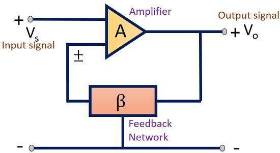
Have a look at the pictorial representation showing how feedback is implemented.
As we know that an amplifier is a device that amplifies the signal. When we talk about an ideal amplifier, there exist some important characteristics like voltage gain, input impedance, output impedance, bandwidth etc.
These parameters of an amplifier are controlled by employing a feedback network. Thus, a feedback network is employed in an amplifier so as to control the gain and other factors of the device.
Feedback amplifiers are basically classified into 2 categories-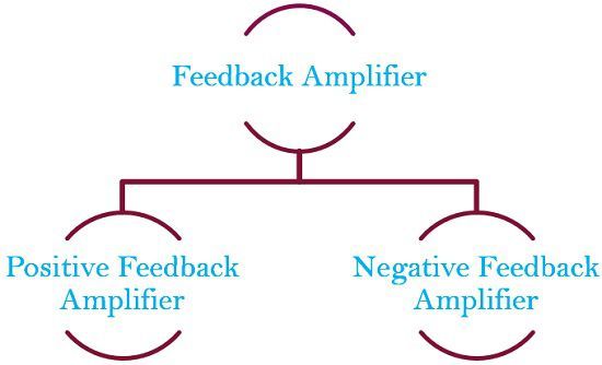
Positive Feedback amplifier– It is a type of an amplifier in which source signal and the feedback signal are in the same phase. Thus, the feedback signal applied increases the strength of the input signal.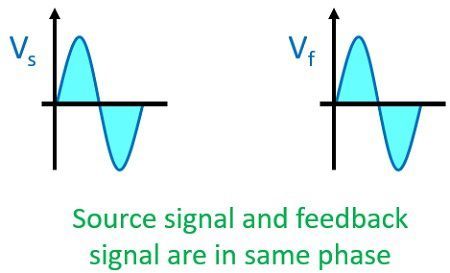
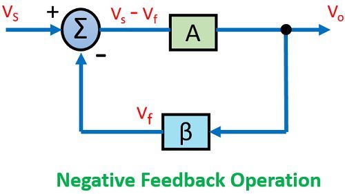
Negative Feedback amplifier– In this type of amplifier source signal and the feedback signal are out of phase with each other. Thus, the feedback signal applied to decrease the strength of the input signal.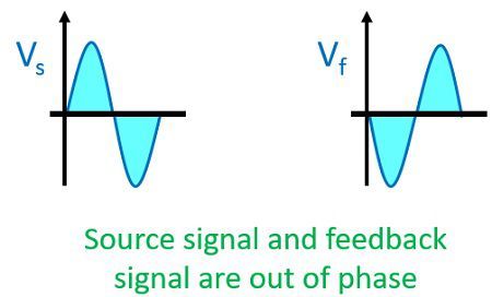
Negative feedback is frequently used in amplifier circuits as positive feedback causes excessive distortion in the circuit which we will discuss later.
Concept of Feedback
The figure shown below represents the block diagram of an amplifier employing feedback network
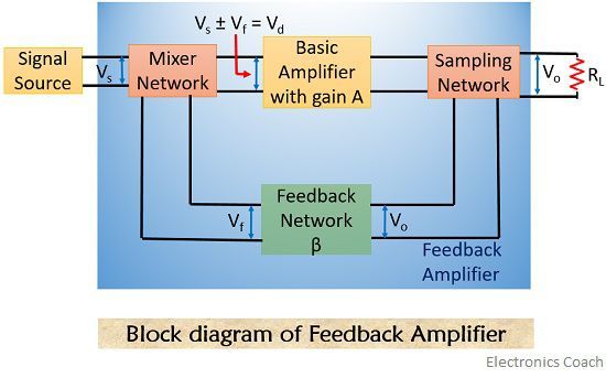 The various blocks of the feedback amplifier section are discussed below-
- Signal Source: The signal source can be a voltage source Vs in series with resistor Rs or it can be a current source Is with parallel resistor Rs.
- Feedback network: A feedback network is a linear two-port network that contains resistors, inductors, capacitors. Its function is to fed back some portion of output to the input.
- Sampling Network: These are basically of two types, current sampling network and voltage sampling network. The output voltage is sampled when we connect feedback network in either shunt or in series with the output.
- Mixer: Mixer circuit is also known as the comparator; it can be a series mixer or shunt mixer. It mixes the source signal and feedback signal thus produces positive or negative feedback for the device.
Operation of Feedback Amplifier
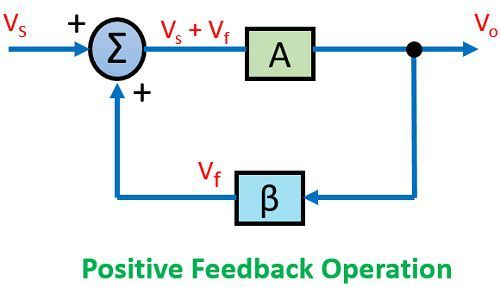
Let us have a look at the diagram shown below-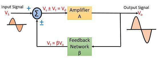
Here, we are talking about the general condition in which we are providing feedback to the input. It can be a positive feedback or a negative one.
An input signal Vs is applied to the amplifier with gain A, that produces an amplified signal, Vo.
A portion or fraction of this Vo is then fed to a feedback network having gain β. The output of feedback network is Vf, this signal is then given to summer or a mixer that resultantly produces either sum or difference of the two signal depending on their phase relationship.
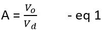
The gain of an amplifier is given as the ratio of output voltage or current to the input voltage or current.
So for the above figure, the gain of the circuit without feedback is given as
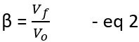
 The gain of feedback network is given as
 But as we can see Vd is the mixer output voltage given by
![]()
The signal voltage Vs and mixer output voltage Vd will only be equal in a feedback amplifier unless the output is not generated.
From Eq 1 we can write as
![]()
Substituting the value Vd in eq 4
![]()
From Eq 2
![]()
Substituting the value of Vf in eq 5
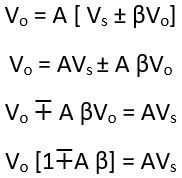
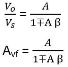 where,
This is the desired value for the gain of the feedback amplifier.
The gain of an amplifier is always greater than 1. This simply means that some elements are present which increases the gain of the amplifier. That element can be a transistor or a MOSFET.
But a feedback network is always a linear network consisting of RLC elements and it does not contain any such amplification device.
That’s why the value of Vf is always less than Vo.
So,β < 1
Let us now discuss amplifier gain in case of negative and positive feedback separately.
As we have discussed earlier that in case of a positive feedback the source signal will be in phase with that of the feedback signal.
Thus, the mixer will produce the summation of the two signal applied to it in case of positive feedback.
So, the gain of the amplifier is given as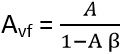
This is the gain for a positive feedback amplifier.
Moving further when we talk about negative feedback amplifier, the source signal and the feedback signal are out of phase with respect to each other.
Thus the mixer circuit will resultantly produce the difference between the two signal in case of a negative feedback amplifier.
So, in this case, the gain of the amplifier is given as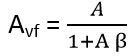
For a negative feedback, the value of denominator is always greater than 1, this will decrease the overall gain of the system by the factor 1 +Aβ.
In case of a positive feedback system, the value of denominator is always less than 1, this will resultantly increase the overall gain by 1 – Aβ.
Gain Stability Relation
For an ideal system, the gain of the amplifier is infinite. Thus, for a smaller input, we will have a much higher value as output. So, such a large gain is not desirable in the circuit.
The system becomes stable only when its gain is small.
Hence, by decreasing the gain the stability of the system increases and vice-versa.
So to have a stable system, the gain of the amplifier must be small and it is achieved by employing negative feedback in the circuit.
Unity Feedback system
Let us now discuss the case where no any feedback network is employed in the amplifier circuit but feedback is provided in the circuit by some physical connection. As we can see in the diagram shown below-
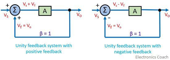
Here, we will have β= 1
So, for positive feedback amplifier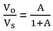
And in case of the negative feedback amplifier
Hence we can say that the gain of an amplifier depends on the type of feedback employed in the circuit.
From the above discussion, we can conclude that a negative feedback is much better than positive feedback.
Morne Alfred says
Thanks very much that is a good one
Adnan Anam says
Thanks a lot for the detailed and basic explanation of the amplifier. The best and easiest explanation one could ever provide.
EMMANUEL QUIST says
l really appreciate it. It has helped me to understand things I didn’t understand at lectures