Definition: Wien Bridge Oscillator is an oscillator which uses RC network so as to produce a sine wave at the output. These are basically the low-frequency oscillator that generates audio and sub audio frequency that ranges between 20 Hz to 20 KHz.
This oscillator circuit uses the Wien bridge to provide feedback with the desired phase shift. It gives highly stable oscillation frequency and does not vary much with supply or temperature variation.
It is basically a two-stage amplifier that consists of an RC bridge circuit or we can say Wien bridge circuit. The Wien bridge feedback network is used so as to make the oscillator sensitive to signal of only a particular frequency.
At this particular frequency, the Wien bridge gets balanced and provides a phase shift of 0⁰. If Wien bridge feedback is not employed, then it will lead to poor frequency stability due to direct coupling. The Wien bridge circuit that we use is a lead-lag network as with the rise in frequency phase shift lags and with the reduction in frequency, it leads.
1 MHz is the maximum output frequency that is provided by this oscillator circuit. In a bridge circuit, the output produced will be in phase with the input only when the bridge is in the balanced condition.
Construction of Wien bridge oscillator
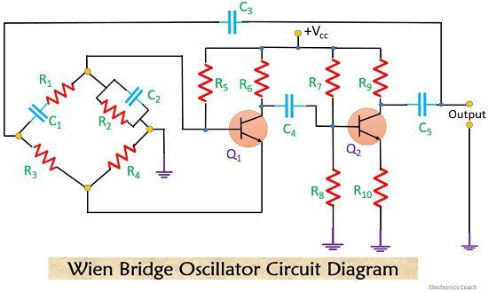
Now, let’s have a look at the circuit diagram of Wien bridge oscillator

The circuit mainly comprised of two transistors Q1 and Q2 and Wien bridge circuit in which a series RC circuit comprising of R1C1 is connected with a parallel RC circuit consisting of R2C2.
At low-frequency range, the reactance of serially connected capacitor C1 is very high due to which it acts as an open circuit that results in blocking of an input signal which resultantly gives no signal at the output.
Similarly, at a higher frequency, the reactance of parallel capacitor C2 becomes very low thus behaving like a short circuit across the output, which again results in no signal at the output.
So, there is a need to choose a frequency point in between the above two conditions that we have discussed right now so that we can achieve the maximum value at the output.
What a resonant frequency is?
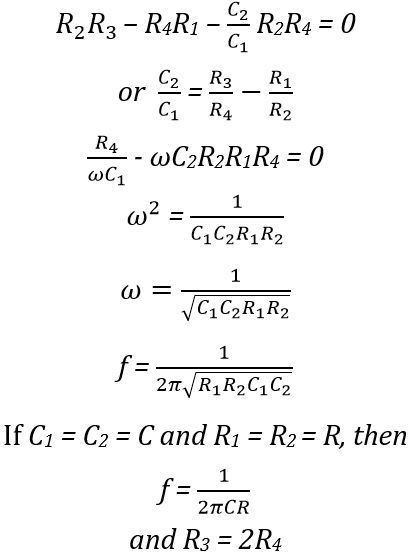
The frequency at which the oscillator provides maximum output is known as resonant frequency. Let’s understand resonant frequency with proper expression-

It can be written as,
![]()
Or
By separating real and imaginary terms we can get

This frequency is known as the resonant frequency of the oscillator. At this frequency the reactance of the circuit becomes equal to its resistance thus the resulting phase difference between input and output will be 0⁰ and in this condition magnitude of output becomes maximum. Other than this frequency the bridge will be in off-balance condition i.e., the fed back voltage and output voltage will not hold correct phase relationship.
Here the transistor Q1 behaves as an oscillator and amplifier whereas, Q2 behaves as an inverter that causes a phase shift of 180⁰.
The circuit uses both positive feedback and negative feedback. The positive feedback is given through R1, C1, R2, C2 to transistor Q1 and the negative feedback is given through voltage divider R3-R4 to emitter section of transistor Q1. The amplitude of the output is stabilized from resistor R3 and R4. Thus, the two transistor that is used, causes a total phase shift of 360⁰ ensuring a positive feedback. The negative feedback ensures a constant output over a range of frequency.
The amplifier voltage gain
Hence, for sustained oscillations, voltage gain A must be equal to or greater than 3.
The negative feedback is essential to have a voltage gain of 3 is not difficult but to have the gain as low as 3 is difficult.
Due to open loop gain limitation of an op-amp, we cannot achieve frequency output above 1 MHz without using special high-frequency op-amps.
Now, by taking an example we can have a better idea of resonant frequency.
Suppose we have resistor R = 20KΩ and capacitor C = 1000pF
So the frequency of oscillations is given by:

Working of Wien bridge oscillator
Firstly, refer to the above-given circuit diagram. The oscillations are set in the circuit by an arbitrary change in the base current of transistor Q1 that can be due to noise or any other type of variation in dc supply. The collector circuit of Q1 amplifies the variation of the base current but with 180⁰ phase shift. This amplified output is then fed to the base of transistor Q2 through an intermediate capacitor C2.
Now, Q2 again amplifies the signal and an amplified and twice phase reversed signal is obtained at the output of transistor Q2. Thus the output will in phase with the input voltage.
A part of the output of Q2 is again fed to the input of the bridge circuit. A part of the forwardly biased signal is supplied across R2 which produces positive feedback or we can say regenerative effect and the part which is applied to R4 produces negative feedback or degenerative effect.
To have sustained oscillations, the effect of regeneration is made somewhat more than that of degeneration at the rated frequency.
The two capacitors C1 and C2 that we have used in the bridge circuit are variable air gang capacitors. We can simply achieve constant frequency by varying C1 and C2 simultaneously.
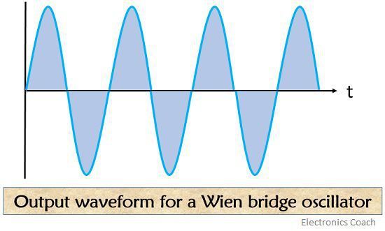
The output waveform of the Wien bridge oscillator is shown below-

Advantages
- It provides a variable frequency range of oscillation which can be achieved by varying the capacitances C1 and C2 simultaneously.
- As the circuit consists of two transistors the overall gain of the system is high.
- Interference due to external magnetic fields does not occur as the inductors are not present in the circuit.
Disadvantages
- The circuit is somewhat complex as it requires two transistors and various other components.
- Due to amplitude and phase shift characteristics, the maximum frequency output is limited or restricted.
The most necessary condition to have the desired signal at the output of the oscillator is the balancing of the bridge so as to have a voltage gain equal to or greater than 3.
Leave a Reply