Definition: LCR meters can be understood as a multimeter, this is because it can measure resistance, inductance, capacitance as per the requirement. Thus, it is termed as LCR meter. L in its name signifies inductance, C stands for capacitance and R denotes resistance.
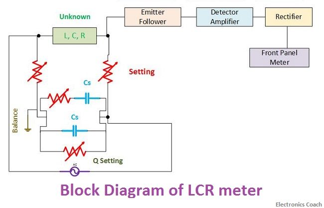
The significant component of LCR meter is the Wheatstone bridge and RC ratio arm circuits. The component whose value is to be measured is connected in one of the arms of the bridge. There are different provisions for the different type of measurements.
For example, if the value of resistance is to be measured, then Wheatstone bridge comes into picture while the value of inductance and capacitance can be measured by comparing it with standard capacitor present in RC ratio arm circuit.

The above block diagram clearly defines the connection diagram of the LCR meter. The measurement of DC quantities will be done by exciting the bridge with DC voltage. On the contrary, the AC measurements require excitation of the Wheatstone bridge with AC signal.
For providing AC excitation, the oscillator is used in the circuit. It generates the frequency of 1 kHz.
Working of LCR Meter
The bridge is adjusted in null position in order to balance it completely. Besides, the sensitivity of the meter should also be adjusted along with balancing of the bridge. The output from the bridge is fed to emitter follower circuit. The output from emitter follower circuit is given as an input to detector amplifier.
The significance of detector amplifier can be understood by the fact that if the measuring signal is low in magnitude, it will not be able to move the indicator of PMMC meter. Thus, in order to achieve the sustainable indication we need to have a high magnitude measuring signal.
But it is often observed that while dealing with the measurement process, the magnitude of the measuring signal falls down due to attenuation factor. The problem to this solution is to utilize an amplifier.
The rectifier is used in the circuit to convert the AC signal into DC signal. When the bridge is provided with AC excitation then at the output end of the bridge the AC signal needs transformation into DC signal.
Front Panel of LCR meter
The component which is to be measured is placed across the test terminals of LCR meter, after which according to the type of component the measurement is performed. To understand the procedure of measurement by LCR meter, the functional controls on front panel needs to be understood.
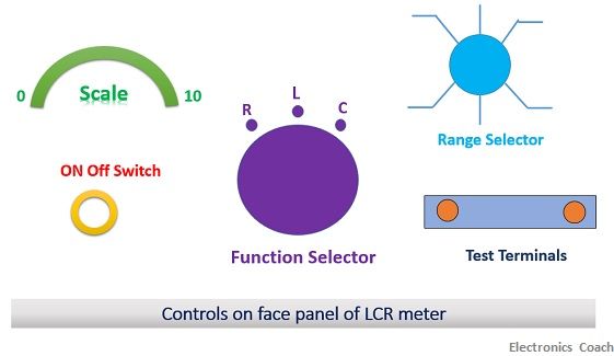
Let’s have a look at the controlling terminals of the front panel of LCR meter.

- ON/OFF Switch: The ON/OFF switch can be used to turn on or off LCR meter. When the switch is positioned to ON state, the main supply is connected with LCR meter. After this, it is crucial to leave the meter for 15 minutes so that it can warm up. The indicator on the front panel will start glowing to indicate that the LCR meter is ON.
- Test Terminals: The two points on the front panel are test terminals. The component which is to be measured is connected to this test terminals.
- Function Selector: The function selector is used for setting the meter in the mode in order to measure the particular type of the component. If resistance is to be measured, then the function selector is to be set at R mode, if inductance is to be measured it is to be adjusted to L mode and similarly in case of capacitance it is to be adjusted at C mode.
- Range Selector: The range selector provides an extent of measuring range so that component of high magnitude or low magnitude values can be measured easily. The range selector should be adjusted properly in order to have correct measurement. For example: if a resistor of 10 mega ohms is under measurement and the range selector is in the range of ohms, then it will not show reliable and accurate results.
The range of instrument can be increased by using multipliers in the circuit. The multipliers should consist of higher precision resistors made up of the metal film. In addition to this, it should possess high-temperature stability.
- Scale: The scale calibrated on the LCR meter will show the final values of the measurement. The indicator will move across the calibrated scale to show the measured value.
Use of meter
When we are measuring the unknown value component, select the range of the LCR meter at the highest value. This is because we do not know the range of the component. After this achieve the null deflection in the bridge by adjusting the range, loss factor and sensitivity.
Protection of LCR meters
One should be extremely careful while providing excitation to the bridge of LCR meter. This is because if the value of the voltage applied to the bridge is high the circuit gets burn out. Thus, for the protection of LCR meter, we can also use a circuit of limiting diodes at the end of the circuit of LCR meter. This will provide over-voltage protection.
Leave a Reply