Definition: The compensation of reactive power of the circuit is quite important as it is associated with the value of the power factor. The reactive power compensation corresponds to the controlling of reactive power to increase the performance characteristics of the AC system. There are some methods by which the power factor of the system can be improved and hence these are regarded as methods of reactive power compensation.
On a practical basis, it is said that the value of the load power factor should be nearly unity as this value is economically viable.
As here we are dealing with reactive power compensation methods thus, let us first understand in brief, what is reactive power?
Reactive power is defined as the amount of power that remains unused and gets generated within an AC circuit or system by the reactive components. This is sometimes called imaginary power. A reactive circuit supplies the amount of power back to the supply which it has consumed thus, the average consumed power of the circuit will be zero. The reason for this is that the same amount of energy flows from source to load back and forth.
The reactive power is regarded as a fundamental part of the total power of the circuit.
It is expressed in a unit called volt-ampere reactive (VAr) with the symbol ‘Q’ and is the product of volt and ampere that are out of phase with respect to each other.
Need for reactive power compensation
We have recently discussed that there is a back and forth movement of reactive power from supply to the reactor in a way that in the first quarter cycle of the AC signal, a capacitor stores the power while in the second quarter cycle, the stored power gets back to the AC source. This to and fro movement of the reactive power between the source and load must be controlled.
Also, the loads in industrial equipment like induction motors, induction furnaces, arc, etc. are the ones that operate at poor power factor while fluorescent tubes, fans, etc. that operate at low power factor requires quite a large amount of reactive power hence the level of voltage at the load terminals get reduced. However, such low voltage at the load terminal is not desirable as this will lead to cause performance impairment of their utility devices.
Due to this reason, the power factor of the system must be necessarily improved using some specific methods.
With reactive power compensation, transmission efficiency is increased. Along with this, the steady-state and temporary overvoltages can be regulated that resultantly avoids disastrous blackouts.
Reactive Power Compensation
A low value of power factor requires large reactive power and this affects the voltage level. Hence in order to compensate for the reactive power, the power factor of the system must be improved.
Thus, the methods for reactive power compensation are nothing but the methods by which poor power factors can be improved. The methods are as follows:
- Using capacitor banks
- Using synchronous condensers
- Using static VAr compensators
Let us now discuss each one separately.
1. Capacitor Banks: In this method, a bank of capacitors forms a connection across the load. As we know that the capacitor takes the leading reactive power, thus this causes the decrease in power taken from the source. This resultantly improves the value of the power factor of the system. This is further classified as series and shunt compensation.
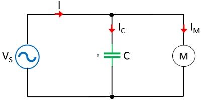
Suppose we have a circuit shown here,
As we have discussed at the beginning itself that the value of the power factor must be unity, thus, to achieve this, here the capacitor across the terminals of the motor must be changed according to the load variation of the induction motor. This is known as dynamic power factor control as reactive power compensation is done by switching in or out of the capacitors at all load conditions.
In order to have a continuous controlling of pf of the system, various small rating capacitors must be required. The switching in and out of the capacitor was done by mechanical switches earlier but now thyristors are used which helps in regulating the flow of reactive power and controlling reactive power voltage by rapid switching of the static capacitors.
2. Synchronous Condensers: Exciting a synchronous motor above a fixed level makes it work as a synchronous condenser or capacitor. It is designed to provide dynamic correction of power factors over the range of its excitation. Initially, when the synchronous motor is under excited then it functions as a lagging power factor thus reactive power is absorbed. While under overexcited conditions, the leading power factor comes into action and starts generating reactive power thus acts as a capacitor.
We have discussed recently static capacitor bank where we have seen that it offers power factor controlling in a discrete manner while in case of synchronous condenser power factor improvement and reactive power flow are of continuous nature.
However, the losses in synchronous condensers are comparatively more than the capacitor bank. Along with this, it offers equipment installation at a single fixed place while capacitor bank offers distributed installation. This increases the effectiveness of the synchronous condenser. The response time of the synchronous condenser is comparatively more than the capacitor bank.
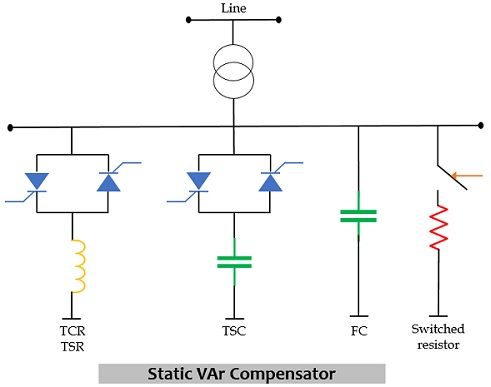
3. Static VAr Compensators: The high voltage power system, makes use of a static VAr compensator. It is abbreviated as SVC and shows improved system stability, reduction in line losses, maintaining the variation within limits. It has shunt reactors and shunt capacitors. Shunt reactors and thyristor-controlled reactors are used for limiting the voltage rise at no load or low load conditions while static capacitors and thyristor switched capacitors are used for preventing the voltage sag at peak load conditions.
This can be formed in two ways, one with the parallel combination of thyristor controlled reactor and fixed capacitor while the other one is the parallel combination of thyristor switched capacitor and thyristor controlled reactor.
SVC is designed to generate as well as absorb reactive power.
Leave a Reply