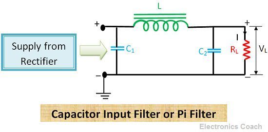
Definition: Pi filter consists of a shunt capacitor at the input side, and it is followed by an L-section filter. The output from the rectifier is directly given across capacitor. The pulsating DC output voltage is filtered first by the capacitor connected at the input side and then by choke coil and then by another shunt capacitor.
The construction arrangement of all the components resembles the shape of Greek letter Pi (π). Thus it is called Pi filter. Besides, the capacitor is present at the input side. Thus, it is also called capacitor input filter.
Significance of Capacitor input filter or Pi filter (π- filter)
The ultimate aim of a filter is to achieve ripple free DC voltage. The filters we have discussed in our previous articles are also efficient in removing AC ripples from the output voltage of rectifier, but Pi filter is more efficient in removing ripples as it consists of one more capacitor at the input side.
Working of Pi filter (π- filter)
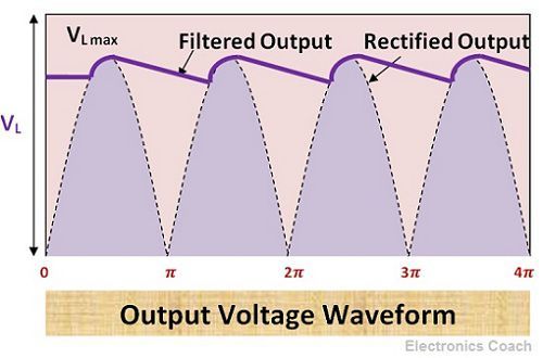
The output voltage coming from rectifier also consist of AC components. Thus it is a crucial need to remove these AC ripples to improve the performance of the device. The output from the rectifier is directly applied to the input capacitor. The capacitor provides a low impedance to AC ripples present in the output voltage and high resistance to DC voltage. Therefore, most of the AC ripples get bypassed through the capacitor in input stage only.
The residual AC components which are still present in filtered DC signal gets filtered when they pass through the inductor coil and through the capacitor connected parallel across the load. In this way, the efficiency of filtering increases multiple times.
In the case of L-section filter, one inductor and capacitor were present so if some AC ripples say 1% is left after filtering that can be removed in Pi-filter. Thus, Pi filter is considered more efficient.
Characteristics of Pi filter (π- filter)
The Pi filter has the characteristics to generate a high output voltage at low current drains. In pi-filters, the major filtering action is accomplished by the capacitor at input C1. The residual AC ripples are filtered by inductor coil L and capacitor C2.
The high voltage is obtained at the output of Pi filter, the reason behind this high voltage output is that the entire input voltage appears across the input capacitor C1. The voltage drop across choke coil and capacitor C2 is quite small.
Thus, this is the advantage of Pi capacitor that it provides high voltage gain. But in addition to this high output voltage, the voltage regulation of Pi filter is very poor. This is because the output voltage drops rapidly with the increase in current flowing through the load.
Apart from the above-mentioned disadvantage, its most crucial advantage is low ripple factor.
Advantages of Pi filter (π- filter)
- High Output Voltage: If you are dealing with the application which requires high output voltage after filtering, then this is the filter you should use. Pi filter’s significance is that it offers low voltage drop across choke coil and capacitor C2 in order to main high output voltage across its output terminals.
- Low Ripple factor: Due to the involvement of 2 capacitors in addition with one inductor it provides improved filtering action. This leads to decrement in ripple factor. A low ripple factor means the ratio of current due to AC ripples and direct Current is low. Thus, a low ripples factor signifies regulated and ripple free DC voltage.
- High PIV: The peak inverse voltage in the case of Pi filters is more in comparison to L-section filter.
Disadvantage of Pi filter (π- filter)
Poor Voltage Regulation: We have discussed above that the output voltage varies with the load current. Thus, this capacitor is not suitable for varying loads. In an application where load current varies, pi filters are not suitable. Thus, in such application, we can use L-section filters as its output voltage do not vary largely with load current.
Application of Pi filter (π- filter)
These are used in communication devices for retrieving the particular signal after modulation. In transmission, the signal is modulated into multiples of high frequency. While on the receiver side, filters are used to demodulate the particular range of frequency.
Rajdeep Barman says
wow,amazing!
Krati P says
Thanks for the appreciation !!!
Anonymous says
Good efforts are always appreciated.
AKASH BHADRA says
It clears my doubt…..and it have a good approach
Krati P says
Thanks for the appreciation !! You can also look at other articles on our website to explore the concepts of electronics.
Ankit says
Great !!
Andrea says
This is awesome 🙂
Rohini E says
Good explanation… Thank you!
Vladi says
Nice article. Thanks.
Right now in my master thesis I am making DC-DC-stepdown converter, where the Pi-filter stands a a basis + other elements (don’t know the names in English yet). When I simulate with Plecs, I can get it to work like a Stepdown converter, if I make the load resistance smaller than 3 Ohm.
What simple (similar to Pi filter) can you suggest instead (or maby as an upgrade) of the Pi filter?
Jaouhar says
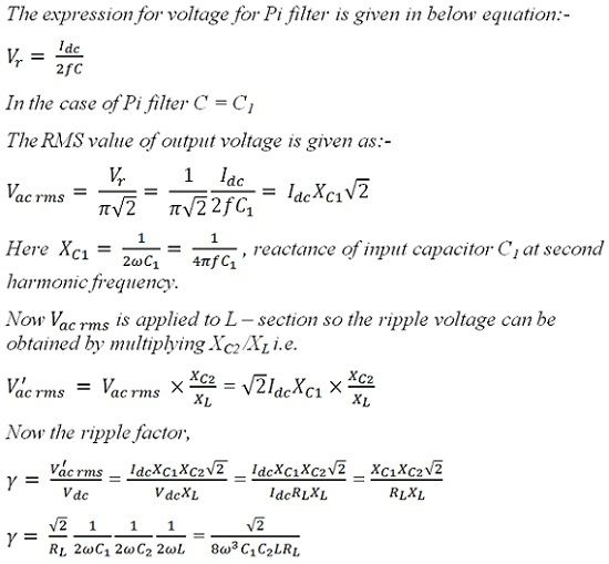
Would you tell me why Vacrms=Vr/(PI*SQRT(2)) and not Vr/(2*SQRT(3)) for the biginning of analysis of Pi filter ?
Uday says
It’s a good explanation about CLC filter👌👌
Sourabh says
Thank you so much Krati P.
A kind request, could you please provide the derivation for expression of output voltage for Pi filter. Also please suggest me a good book on filters which I can refer to for in-depth knowledge of all filters.
Thanks again, Have a wonderful day!