Phase Difference is defined as the delay between two or more alternating quantities while attaining the maxima or zero-crossings giving rise to the difference in their phases. This difference in two waves is measured in degrees or radians and is also known as phase shift.
It is sometimes defined as the difference between two or more sinusoidal waveforms in consideration with a reference axis. It is denoted by φ and corresponds to the shift in the waveform along the horizontal axis from a common reference point.
We will discuss the phase difference of AC circuits in detail later first let us understand-
What is Phase?
The phase of alternating quantities is defined in terms of displacement and time period. In terms of displacement, phase represents the angle from a reference point by which the phasor representing the alternating quantity travels up to the point of consideration.
To understand this, have a look at the figure given below:
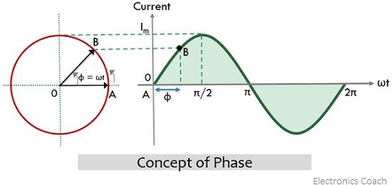
In the above figure, the x-axis is the reference axis and at instant A, the phase φ of the alternating quantity is 0⁰ while under displacement, the phase of the same quantity at instant B represents the angle (in degrees or radians) through which the phasor has traveled considering the same reference axis i.e., x-axis. Generally, the phase of the alternating quantity varies from 0 to 2π in rad or 0⁰ to 360⁰.
Furthermore, in terms of the time period, the phase at any particular instant is defined as the fraction of the time period through which it is advanced with respect to the reference instant. Consider the waveform representation given below:
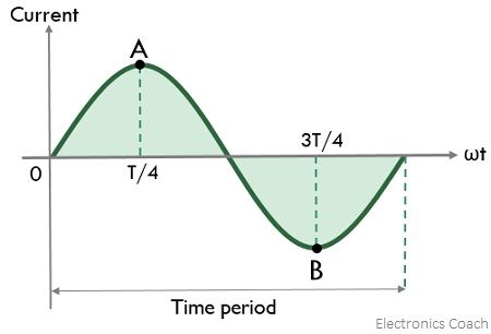
Here 0 is considered as the reference instant, thus, the phase of the alternating quantity at A is T/4 while at B is 3T/4.
Concept of Phase Difference in AC Circuits
Suppose a comparison between 2 alternating quantities is made according to the overlapping of their peaks and zero crossings.
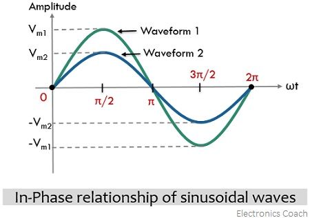
So, when the peak and zero crossings of alternating quantities with same frequency coincide then such quantities are said to be in phase. More simply, we can say, that, when two alternating quantities of same frequency reach their maximum positive, negative, and zero values at the same instant of time during one complete cycle irrespective of their amplitude then such quantities are said to have a similar phase. This explanation is clearly shown in the figure given below:
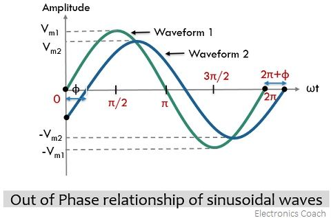
Conversely, when the peak and zero crossing of the alternating quantities with same frequency do not coincide then these quantities are said to be out of phase with respect to each other and a specific difference in the phase exists between the two. In a nutshell, we can say, when two alternating quantities of the same frequency attain their positive and negative peaks and zero values at different time instants in one complete cycle, considering the same reference axis, then there exists a phase difference between them. The out of phase relationship between two alternating quantities is clearly shown in the figure below:
Equation for Phase Difference
The general equation of the alternating quantities is given as:
![]()
: φ represents the phase of the alternating quantity,
Am is the amplitude of the waveform,
ωt represents the angular frequency of the waveform.
Here the φ can be either positive or negative.
Now, the question arises, when φ is positive, and when it is negative?
Before understanding positive and negative phase shifts, understand the condition for zero phase difference.
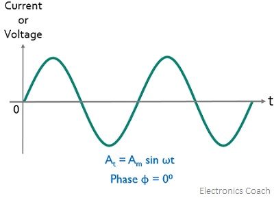
So, when the phase of the alternating quantity is 0 then the instantaneous value of the sinusoidal quantity is at t = 0 which is considered as reference. The figure given below indicates φ = 0⁰.
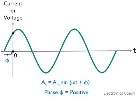
Positive Phase Shift: When an alternating quantity begins before t=0 which is considered as reference, then the positive slope of the alternating quantity is shifted towards the left thereby crossing the horizontal axis before the reference. Thus, in such a case, φ>0 and the angle will be positive in nature. This gives rise to a leading phase angle.
This can be said conversely as, in the case of a positive phase, the alternating quantity has some positive instantaneous value at t = 0. This is clearly shown below:
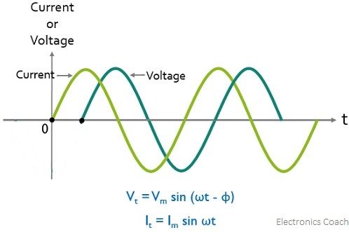
In the below-given figure, one is the voltage waveform which is started before the reference point and the other is the current waveform which exactly starts at t=0 i.e., reference. Generally, in a purely inductive circuit, voltage leads the current.
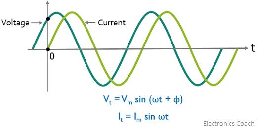
Here the current is lagging voltage by angle φ.
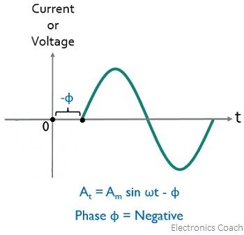
Negative Phase Shift: When the alternating quantity starts after t=0 i.e., reference point, then its positive slope is shifted towards the right and so crosses the horizontal axis after the reference point. Therefore, here φ<0, and the angle will be negative in nature. When the phase angle is negative then it represents a lagging phase angle.
For the negative phase, the alternating quantity has some negative instantaneous value at t = 0, as represented here:
In the figure given below, we have current and voltage waveforms, and it is clearly shown that the voltage waveform is started after the reference and the current waveform is started exactly at the reference. Generally, in purely capacitive circuits, current leads the voltage.
Here voltage is lagging current by angle φ.
The relationship between voltage and current sinusoidal waveforms is very important while dealing with AC circuits as these form the base of AC Circuit analysis.
Leave a Reply