Definition: Phase-locked loops are the circuits used to maintain synchronization between input and output frequency of oscillator circuits by comparing the difference in phase of the two signals. With the evolution of IC, it has emerged as the basic building block of electronic circuits.
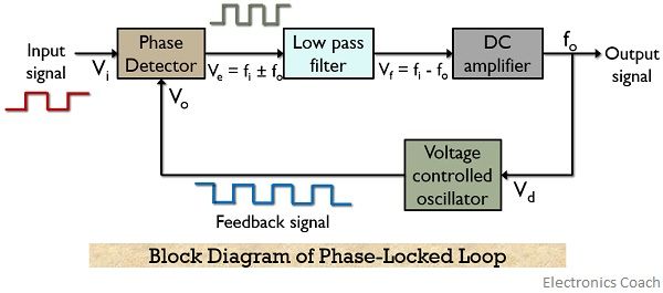
Phase-locked loops are abbreviated as PLL and are basically a feedback circuit comprising of a phase detector (or comparator), a low pass filter and voltage-controlled oscillator along with an amplifier.
Though various applications are associated with PLLs, one of the major applications of PLL circuits is in coherent detection of the signal. This is so because PLL is used to eliminate phase errors that get introduced at the time of modulation.
Phase errors are usually associated with the carrier signal at the time of modulation. So, when the carrier signal is multiplied with the message signal then it results in the distorted signal at the receiving end.
Therefore, the receiver circuits use a phase-locked loop to remove the phase error associated with the signal.
Block Diagram and Working of Phase-Locked Loop
The figure here represents the basic block diagram of a phase-locked loop circuit:

Let us now move further and understand how each block inside a PLL circuit operates in order to eliminate the phase error between two signals.
Phase Detector
A phase detector is nothing but a comparator here. It performs a comparison of two frequency component fed at its input and generates a dc voltage. This generated voltage is proportional to the difference in phase of the two frequencies.
Usually, the frequency applied to the PLL is digital frequencies.
Now as we can clearly see in the figure shown above that through a feedback path the output of the VCO is provided to the phase detector. This fed back signal acts as the second input of the comparator.
The phase detector performs a comparison of the frequency of actually applied digital input signal with the frequency of feedback signal. The output generated is a dc voltage (also called error voltage, Ve) whose amplitude is proportional to the phase difference of the two signals applied at the input.
Low-pass filter
The output of the phase detector is provided to a low pass filter, that eliminates the high-frequency component and noise from the output of the comparator.
The phase detector gives the sum and difference frequency of two input signals as its output.
The sum component of two frequencies (i.e., fi + fo) is a high-frequency component thus is eliminated by the LPF. While the difference (i.e., fi – fo) is a low-frequency component which is passed by the filter.
This low-frequency dc voltage signal is then provided to a dc amplifier which amplifies the signal level. This amplified signal is then provided to the VCO.
Voltage Controlled Oscillator
The output of LPF acts as a control signal to the VCO. The VCO generates a dc signal, the amplitude of which is proportional to the amplitude of output of LPF.
Here the adjustment in the output frequency of VCO is made until it shows equivalency with the input signal frequency.
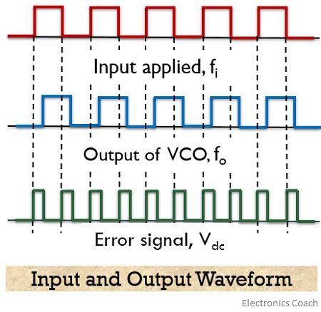
The input applied and output generated of a PLL circuit is shown below:

Basically the PLL tries to adjust the frequency of the output signal. Thus this adjustment process includes 3 major stages, which are free-running, capture and phase lock stage.
When the difference of frequencies of the two inputs is 0, showing a constant phase difference then it is said that the loop is locked.
In case there exist a phase shift of 180⁰ between the two signals, then the output voltage will be maximum.
In the absence of an input signal, the generated output voltage will be zero, allowing the VCO to operate at a set frequency. This frequency is known as the free-running frequency of the oscillator.
Applications of PLL
Phase-locked loop finds their use in frequency multiplication circuits or a frequency synthesizer. The indirect method of synthesis uses PLL. It also finds applications in frequency demodulating circuits and FSK demodulators.
Leave a Reply