Definition: Phase shift oscillators are the oscillators that generate a stable sinusoidal signal at the output. Basically, the circuit has, an amplifier unit like transistor or op-amp along with a feedback network comprising of resistors and capacitors. Thus, is also known as RC phase shift oscillator.
The RC network is present in the feedback path is connected in ladder fashion thus also known as ladder RC phase shift oscillator. We know for an RC circuit; the output voltage leads the input for a sinusoidal waveform.
However, the phase angle by which the output leads the input relies on the values of R and C component.
We know to have sustained oscillations,
- The loop gain of the oscillator must be equal to 1.
- And the phase shift introduced by the circuit must be equal to 0 or 360⁰.
The amplifier circuit generates a phase shift of 180⁰. So, in order to achieve sustained oscillations, in RC phase shift oscillator, the feedback path must also provide a phase shift of 180⁰. Thus the achieved overall phase shift can be either 0 or 360⁰.
Also, loop gain equal to 1 can be achieved by tuning the gain of the amplifier and feedback circuit.
Let us first understand how the phase shift is being generated by the oscillator.
RC Feedback Network
The figure below represents an RC phase shift feedback network, having a resistor and capacitor: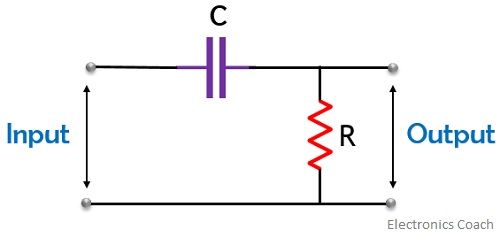
As we have already discussed that output leads the input in this case, thus, is also known as a phase lead circuit.
From the above circuit, we can say that the transfer function of the circuit is given as
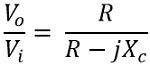
We know, XC = 1 / ωC
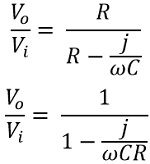
So, the phase shift will be given as
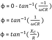
Thus by observing the above expression, we can clearly say that the phase shift depends on the value of R and C.
So, for a very small value of XC, φ will be equal to 0⁰. But when R is very small or 0 then it will cause XC/R to get equal to infinity, thus in this case φ will be 90⁰.
Hence from the above discussion, it is clear that the feedback circuit provides a phase shift between 0 to 90⁰.
But as we have already discussed that we require to have a feedback network that can provide us with a phase shift of 180⁰ in the phase shift oscillator. Thus the value of R in the circuit must be kept as low as possible, more specifically 0.
Suppose we have formed cascade connection of two RC stages, where each stage is providing a phase shift of 90⁰. Thus combinely we can have a phase shift of 180⁰. But in that case, if the value of R is 0, then the gain of the circuit will also be 0.
So, practically, one cannot have a phase shift of 180⁰ only by using 2 stages of phase shift oscillator. Thus to achieve a phase shift of 180⁰, despite using 2 RC stages we use 3 RC stages where each stage separately provides a phase shift of 60⁰.
The figure below represents the feedback network having 3 RC stages:
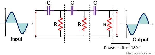
As we have already discussed that to have the overall phase shift of 360⁰ around the loop, the feedback circuit must provide a phase shift of 180⁰. And in case of 3 RC stages, each stage must provide a phase shift of 60⁰.
It is to be noted here that the values of resistance and capacitance must be the same for each stage. So that each section of the feedback circuit produces a desired phase shift for a particular frequency.
Phase Shift Oscillator Using Op-amp
The figure given below shows the circuit of an RC phase shift oscillator:
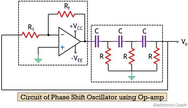 As we can see that the output of the inverting amplifier is applied to the feedback network. This signal which is fed back to the amplifier drives it further. Thus we achieve the total phase shift of 360⁰ around the loop. Hence the condition for positive feedback is achieved thereby causing the circuit to act as an oscillator.
The expression for the frequency of oscillations is given as
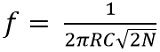
: N is the total number of stages
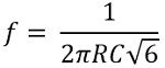
Thus for 3 stages, the frequency of oscillations will be
Let us now move further and derive the expression for attenuation provided by the RC phase shift network.
Consider the figure below:
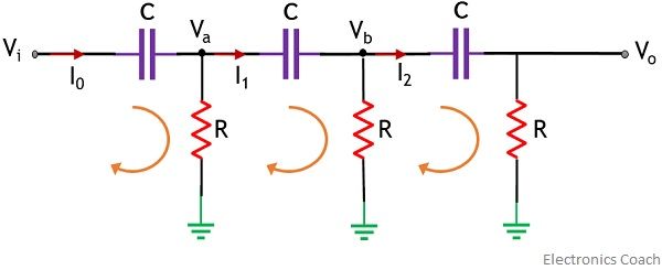
Here, Va and Vb are the voltage at the two nodes, while I0, I1 and I2 denote the current that is flowing through the 3 capacitors.
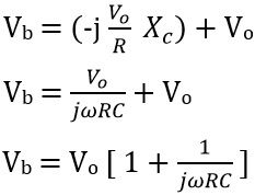
At node Vb,
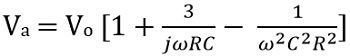
The overall voltage will be equal to the sum of output voltage Vo and drop across the capacitor. Thus we have
![]()
Since![]()
thus![]()
Therefore,
On applying KCL,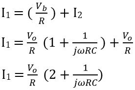
Further,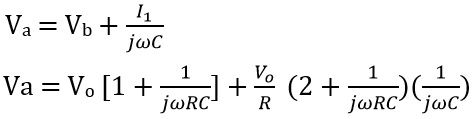
On solving we get
Now applying KCL at Va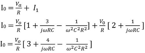
Now,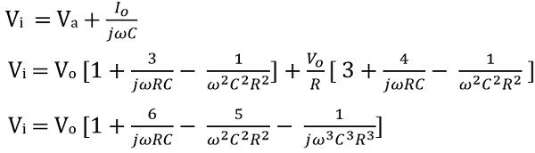
On equating the imaginary part, we get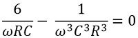
Therefore, on transposing and further solving we will get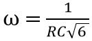
So,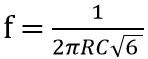
And on equating the real part we get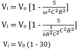
Hence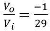
Thus we can say that the network is providing attenuation -1/29. Here, the negative sign indicates that there exists a phase shift of 180⁰. Usually, in RC phase shift oscillator, the value of R is kept constant and only C is kept variable, so as to have the desired frequency of oscillation.
This is all about RC phase shift oscillator.
Leave a Reply