The major difference between high pass and low pass filter is the range of frequency which they pass. If we talk about high pass filter, so it is a circuit which allows the high frequency to pass through it while it will block low frequencies. On the contrary, low pass filter is an electronic circuit which allows the low frequency to pass through it and blocks the high-frequency signal.
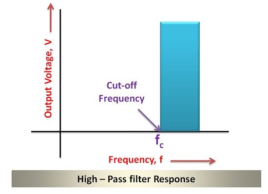
You might be thinking, what range of frequency is high and which is low? There is a term defined for filters, i.e. cut-off frequency, it assumes a threshold value. The high pass filter offers low reactance to signals with the frequency above this cut-off frequency and provides high reactance to frequencies below this cut-off frequencies.
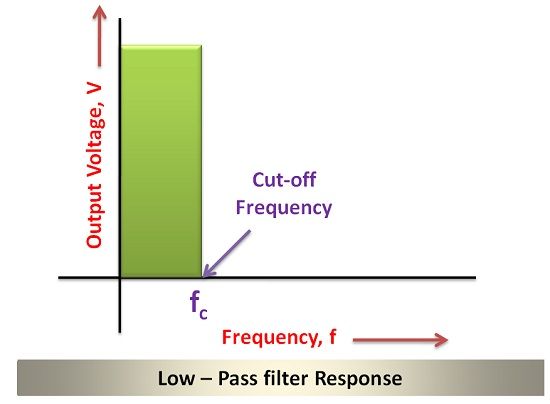
The low pass filter offers low reactance to the signals with frequencies lower than the cut-off frequency so that low frequencies can pass but it provides high reactance to the high-frequency signal and thus block them.
Before embarking on the operational mechanism of the filter, let’s put light on the components of the filter. If you are designing a filter, either high pass filter (HPF) or low pass filter (LPF), you need electronic components such as a resistor, capacitor, amplifier etc.
The point to be noted here is if you are utilizing the passive components such as a resistor, capacitor etc. the resultant filter will be termed as the passive filter. While if you are planning to use the amplifier in your filter circuit to increase the gain of the filtered signal, then you are designing a filter which can be termed as an active filter.
So far we have discussed the crucial difference between high-pass and low-pass filter along with the components which make it active or passive. Let’s discuss other significant differences with the help of comparison chart.
Content: High Pass and Low Pass Filter
Comparison Chart
| Parameters | High Pass Filter | Low Pass Filter |
|---|---|---|
| Definition | It is a circuit which allows the frequencies above cut off frequency to pass through it. | It is a circuit which allows the frequency below cut off frequency to pass through it. |
| Circuit Architecture | It consists of Capacitor followed by a resistor. | It consists of resistor followed by capacitor. |
| Significance | It is significant when the distortion due to low frequency signal such as noise is to be removed. | It is significant in removing aliasing effect. |
| Operating Frequency | Higher than the cut off frequency. | Lower than the cut off frequency. |
| Applications | In audio amplifiers, low noise amplifiers etc. | In communications circuit as anti-aliasing filter. |
Definition
High Pass Filter
A high pass filter attenuates the low-frequency signal and allows only high-frequency signal to pass through it. Although it offers attenuation to high-frequency signal too but the attenuation factor is so small that it can be neglected.
You must be thinking what is the designing process of High Pass filter, what makes it allow signals of high frequency to pass through it and blocking the signals of low frequency. This is possible by utilizing the characteristics of capacitor and resistor.
The input signals are applied to the capacitor, and then the voltage across the resistor is obtained as the output voltage. The combined term for the resistance of resistor and resistance of the capacitor is termed as reactance.
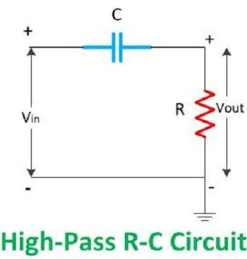
In the above circuit, it is evident that a capacitor is connected to the resistor.
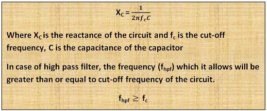
It is quite clear from the above equation that the reactance is inversely proportional to the cut off frequency. If the frequency of the input signal is high, then the reactance will assume lower value. But if the frequency of the signal is low, the reactance will be high.
I hope now you understood that why a high pass filter allows the high frequency to pass through it while blocking the low frequency.
Low Pass Filter
In a low pass filter, the position of capacitor and resistor is interchanged so that the desired output can be obtained. When the input is applied to low pass filter circuit, then the resistance will offer the constant obstruction, but the position of capacitor affects the output signal.
If the high-frequency signal is introduced in the low pass circuit, so it will pass from resistance which will offer it the usual resistance, but the resistance offered by capacitor will be zero. This is because the resistance offered by the capacitor to high-frequency signal is zero while to the low-frequency signal is infinite.
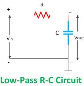
It is clear from the circuit diagram that if high-frequency signal enters low pass filter circuit than the capacitor will allow it to pass and it will be passed to ground. In this condition, the output voltage obtained is zero as the entire voltage is passed to ground.
But if low-frequency signal enters the low pass filter circuit then it will generate the output, because the resistance will offer the same obstruction as in the case of high-frequency signal bt the capacitor will provide infinite resistance.
Thus, in this condition, the signal cannot pass through the capacitor path. Thus he entire low-frequency signal is passed to the output terminal.
Key Differences between High Pass and Low Pass Filter
- The key difference between high pass and low pass filter is that the high pass filter circuit passes signals of the frequency higher than the cut off frequency while the low pass filter passes signals of the frequency lower than the cut off frequency.
- The high pass and low pass filter also vary in circuit designing; high pass filter consists of capacitor followed by resistance in parallel. While low pass filter circuit consists of resistor followed by the capacitor.
- The low pass filter is used as anti-aliasing filter while the high pass filter is used in audio amplifier for coupling or removing distortions due to low-frequency signal such as noise.
Conclusion
The high pass and low pass filter we have discussed above are passive filters as they use passive components. We can increase the gain of the signal by using amplifiers in the filter circuit then it will become an active filter.
gilab says
nice expression