Definition: Piezo-electric transducers are the devices that change electrical charges, generated by the application of mechanical force into electrical potential. The voltage generated by piezoelectric transducers is the effect of the displacement of charges.
Piezo-electric transducers are based on the principle of the piezoelectric effect.
The voltage is given as:
Piezo-electric Effect
As we have discussed that these transducers operate on the principle of the piezoelectric effect and here the word piezo means stress or force. The higher the force, higher will be the voltage at the output. The electric potential can be easily measured by voltage measuring devices.
Piezo-electric materials possess the property of piezoelectricity. Due to this property, the potential appears across the surface of a crystal of piezo-electric material if the dimensions of crystals are changed.
This effect is reversible i.e. if a varying potential is given at a proper axis, it will automatically variate the dimensions of the crystal which leads to deformation of the crystal.
The elements that demonstrate piezo-electric qualities are called electro-resistive elements.
Some commonly used piezo-electric materials include Rochelle salts, ammonium dihydrogen phosphate, quartz, lithium sulphate etc. Quartz crystal shows unique property by generating the electrical voltage on applying mechanical stress to it.
Quartz and Rochelle salt belongs to the natural group. The nature of ceramic materials is polycrystalline and made up of barium titanate. In originality, they do not have piezo-electric properties but proper polarizing treatment is used for the production of such properties.
In a nutshell, a piezo-electric transducer changes mechanical motion into electrical signals because mechanical motion generates charges and this charge appears as a voltage. This effect is direction sensitive.
The Piezo-electric crystal is shown below: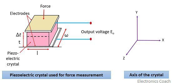
The magnitude and polarity of charges generated at the surface of crystal are proportional to the magnitude and direction of the force applied.
Charge, Q = d Χ F coulomb
: d = charge sensitivity of the crystal; C/N
F = applied force, N
The thickness of the crystal changes on application of force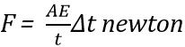 : A = area of crystal in m2
t = thickness of crystal in m
E = Young’s modulus, N/m2
Young’s modulus is given by:![]()

A = ωl
: ω = width of crystal in m
l = length of crystal in m
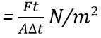
By substituting the value of “force” in the “charge equation”:![]()
Now, due to this charge, we will have an output voltage : Cp = capacitance between electrodes
And it is given by![]()
Substituting the value of in we will get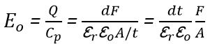
But we know that So,
So,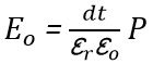
![]()
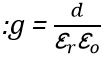 g is the voltage sensitivity and its unit is Vm/N
Now, 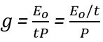
But, E0/t= electric field strength, V/m
Let ε = E0/t = electric field
Crystal voltage sensitivity is the ratio of electric field intensity to the pressure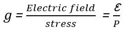
Sometimes it is better to express the output voltage in terms of deflection inspite of force. This is so because deformation is the real reason for charge generation.
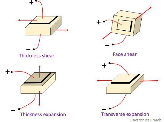
Modes of operation of the piezo-electric crystal
The operational modes are as follows-
- Thickness shear
- Face shear
- Thickness expansion
- Transverse expansion
The modes are shown below:
Properties of piezo-electric crystals
- The piezo-electric material shows high stability.
- This material has high output insensitivity to temperature and humidity.
- These are able to be formed into most desirable shape.
- The equivalent circuit of the Piezo-electric transducer.
The basic circuit is shown below:
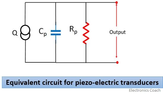
Here, Q = dF
Charge generation is across Cp and Rp is the leakage resistance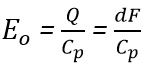
Applications
- These materials are used in dynamic measurements.
- These are used in stabilizing electric oscillators.
- It is used in microphones and speaker.
- It is used in the ultrasonic generator.
Advantages
- Due to its small size, it is easy to handle.
- It shows high frequency respectively as the parameter changes rapidly.
- It does not require any external force.
Disadvantages
- The received output is low.
- It is difficult to provide the desired shape to the crystal.
It is required to have an external circuit associated with it as the output produced by the piezo-electric transducer is low.
Leave a Reply