Definition: Strain gauge is a device which is when subjected to some force results change in resistance of the material. The change in resistance is measured in terms of either load or displacement. It basically measures strain on the application of stress. Strain gauge directly is used for the measurement of load and indirectly it is used for the measurement of displacement.
The strain gauge was invented in 1938, by Edward E Simmons and Arthur C Ruge.
Strain gauges are employed as secondary transducers in many detectors and transducers. Such as load cells, torque meters, temperature sensors, accelerometer etc.
Theory of Strain Gauge
Let us take a wire having length ‘L’ and cross-section area ‘A’
The resistance of the wire will change if the wire is stretched or compressed. This is due to dimensional change and the property of material called the piezo-resistive effect.
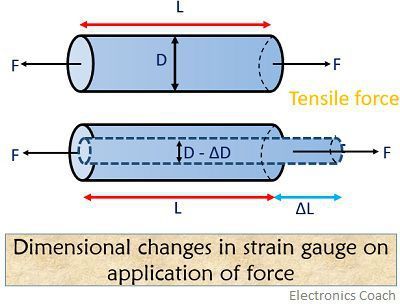 Piezo-resistive effect states that change in dimensions of the conductor resultantly changes its resistance. Resistance strain gauges are also known as piezo-resistive gauges.
The resistance is given by![]() ρ = resistivity of the material,
ρ = resistivity of the material,
L = length of material,
A = cross-sectional area of material
On differentiating resistance equation, we will have
![]()
Axial strain is given as-
![]()
The transverse strain is given as-
![]()
Poisson’s ratio is
ν = lateral strain/ longitudinal strain
The volume of wire is![]()
On differentiating![]()
Moreover,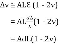 Since,
![]()
Therefore,![]()
![]()
So,![]()
As we know,![]()
Substituting the value of L dA in above equation,
![]()
Therefore,![]()
Dividing the above equation by![]()
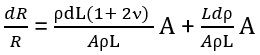
Resultantly we will have,![]()
Gauge factor is given by,
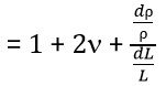 : 1 = resistance change due to change in length
2ν = resistance change due to change in the area
![]() = resistance change due to piezo-resistive effect
= resistance change due to piezo-resistive effect
When strain is neglected,![]()
The above equation is valid only when the piezo-resistive effect is almost negligible.
The value of Poisson’s ratio for all metals is between 0 to 0.5, that gives a gauge factor of value approximately 2.
Types of Strain Gauge
The strain gauge is basically divided into following categories-
- Unbounded metal strain gauge
It is a type of gauge in which a wire is stretched in an insulating medium in between two points. The insulating medium can be air.
The wire can be made of alloys such as copper-nickel, chrome nickel, nickel-iron having a diameter of about 0.003 mm. The gauge factor for this category of the strain gauge is about 2 to 4 and sustain a force of 2mN.
These are almost exclusively used in transducer applications where preloaded resistance wires are connected in a Wheatstone bridge configuration.
2. Bonded wire strain gauge
Along with the construction of transducers, a bonded metal wire strain gauge is used for stress analysis. A resistance wire strain gauge has a wire of diameter 0.25mm or less.
The grid of fine resistance wire is cemented to carrier. It can be a thin sheet of paper, Bakelite or a sheet of Teflon.
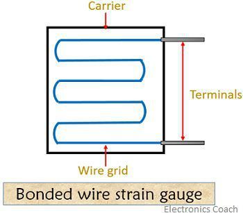
To prevent the wire from any mechanical damage, it is covered on top with a thin sheet of material. The spreading of wire allows us to have a uniform distribution of stress over the grid.
The carrier is bonded with an adhesive material. Due to this, a good transfer of strain from carrier to a grid of wires is achieved.
A resistance wire strain gauge must possess the following characteristics in order to have desirable results-
- The strain gauge should have a high value of gauge factor. As high gauge factor indicates a large change in resistance, that leads to high sensitivity.
- The gauge resistance should be high so as to minimize the effect of undesirable variations of resistance in measurement circuits.
Typically, the resistance of strain gauges is 120Ω, 350Ω, 1000Ω. But a high resistance value results in lower sensitivity. Thus to have higher sensitivity, higher bridge voltages have to be used.
- The strain gauge should have low resistance temperature coefficient.
- It should possess linear characteristics in order to have the constancy of calibration over its entire range.
- Strain gauges must have a good frequency response. The linearity should be maintained within accuracy limits.
3. Bonded metal foil strain gauge
This category is just an extension of previously defined, bonded metal wire gauge. These metal foil strain gauge uses similar materials to wire strain gauges. These are widely used in stress analysis applications and for many transducers.
The figure below shows a typical bonded metal foil strain gauge-
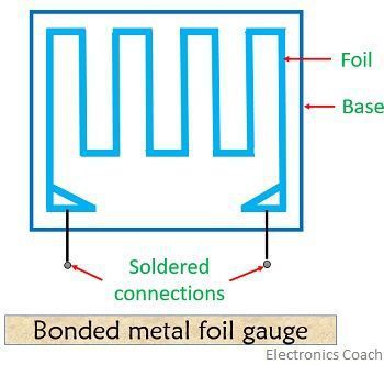
Foil type gauges have higher operating temperature range. This is so because it has much higher heat dissipation capacity as compared to wire wound strain gauges. This is due to their greater surface area for the same volume.
The large surface area resultantly leads to better bonding.
4. Semi-conductor strain gauge
The action of a semiconductor strain gauge depends on piezo-resistive effect i.e., the change in resistance due to resistivity.
These are mainly used in conditions where high gauge factor and small envelope are required. The resistance of semiconductor changes with the change in applied strain.
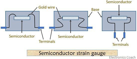
As the name indicates the semiconductor strain gauges use semi-conducting materials. Such as silicon and germanium for their construction.
Typical strain gauge material has a crystal material that is strain sensitive along with leads sandwiched in a protective matrix.
Advantages of semiconductor strain gauge–
- They have a higher value of gauge factor of about ±130.
- These offer excellent hysteresis characteristics of semi-conductor.
- They have a small length ranging from 0.7 to 7mm.
- These are very helpful in the measurement of local strain.
Disadvantages of semiconductor strain gauge–
- These are highly sensitive to change in temperature.
- Semi-conductor strain gauge possesses poor linearity.
5. Diffused strain gauge
This category of the strain gauge is basically used in transducers. Here, the diffusion process is employed which is used in IC manufacturing. In pressure transducers, these are used as sensing elements.
Strain Gauge temperature compensation
The figure below shows strain gauge temperature compensation circuit-
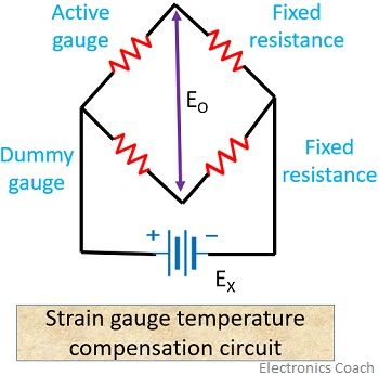
Here, the active gauge will be subjected to strain but dummy gauge will not be subjected to strain. The temperature of both active and dummy gauge must be kept constant.
The change in resistance is always measured by Wheatstone bridge. There are basically two types of measurement- one is using balanced bridge other is using an unbalanced bridge.
Let’s have a look at the balanced bridge circuit shown below-
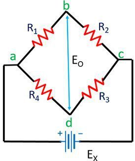
For the bridge to be balanced, points ‘b’ and ‘d’ must be at the same potential.
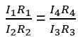
I1R1 = I4R4
I2R2 = I3R3
Diving the above 2 equations
In case of no current in the detector
I1 = I2 and I3 = I4
So, 
Let R1 = Rx
![]()
This simply means that either R4 or R2 can be used to compensate the temperature.
It is sometimes called ambient temperature compensation.
Applications of the strain gauge
- It is used to determine the stress produced by machinery.
- During component testing, strain gauges are used.
- In the field of civil engineering, strain gauges are used to keep rails in good condition.
- A torque on an engine is measured when a strain gauge is attached to a dyno.
- Strain gauges are used for measurement of strain and its associated stress in experimental stress analysis.
As we know gauge factor is the ratio of fractional change in resistance to the change in length. So, for a metallic strain gauge, the gauge factor is usually 2.
Leave a Reply