Definition: A modulation technique that allows variation in the position of the pulses according to the amplitude of the sampled modulating signal is known as Pulse Position Modulation (PPM). It is another type of PTM, where the amplitude and width of the pulses are kept constant and only the position of the pulses is varied.
Simply put, the pulse displacement is directly proportional to the sampled value of the message signal.
To understand the generation of the PPM signal, it is necessary to understand Pulse Width Modulation (PWM or PDM). PWM is the first type of PTM and is discussed in the previous content.
Basics of Pulse Position Modulation
The information is transmitted with the varying position of the pulses in pulse position modulation.
The basic idea about the generation of a PPM waveform is that here, as the amplitude of the message signal increases, the pulse shifts according to the reference.
As we have already discussed in PWM that due to the variable width of the pulses, the transmission power also varies accordingly. However, this is not the case with PPM as here the width of the pulses remains constant and only their position varies. Thus, transmission power does not show variation.
Now, the question arises how the position of the pulses show variation?
As we have already discussed that a PPM signal is generated in reference to a PWM signal. Thus, the trailing edge of the PWM signal acts as the beginning point of the pulses of PPM signal.
Block diagram for generation of PPM signal
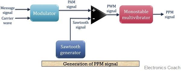
As we have already discussed that a PPM signal can be easily generated by making use of a PWM signal. Thus, here we have assumed that a PWM signal is already generated at the output of the comparator and now we have to generate a PPM signal.
The figure below shows the block diagram for generating a PPM signal:
 Here, we have made a detailed block diagram where first, a PAM signal is produced with is further processed at the comparator in order to generate a PWM signal.
The output of the comparator is fed to a monostable multivibrator. It is negative edge triggered. Hence, with the trailing edge of the PWM signal, the output of the monostable goes high.
This is why a pulse of PPM signal begins with the trailing edge of the PWM signal.
It is to be noted in case of PPM that the duration for which the output will be high depends on the RC components of the multivibrator. This is the reason why a constant width pulse is obtained in case of the PPM signal.
With the modulating signal, the trailing edge of PWM signal shifts, thus with that shift, the PPM pulses shows shifts in its position.
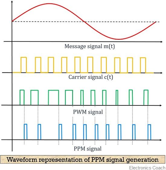
The figure below shows the waveform representation of the PPM signal:

Here, the first image shows the modulating signal, and the second one shows a carrier signal. The next one shows a PWM signal which is considered as reference for the generation of PPM signal shown in the last image.
As we can see in the above figure that the point of ending the PWM pulse and the beginning of PPM pulse is coinciding, which can be clearly seen from the dotted line.
Detection (Demodulation) of PPM signal
The figure below shows the block diagram for the detection of a PPM signal at the receiver:

As we can see in the above figure that the demodulation circuit consists of a pulse generator, SR flip-flop, reference pulse generator and a PWM demodulator.
The PPM signal transmitted from the modulation circuit gets distorted by the noise during transmission. This distorted PPM signal reaches the demodulator circuit. The pulse generator employed in the circuit generates a pulsed waveform. This waveform is of fixed duration which is fed to the reset pin (R) of the SR flip-flop.
The reference pulse generator generates, reference pulse of a fixed period when transmitted PPM signal is applied to it. This reference pulse is used to set the flip-flop.
These set and reset signals generate a PWM signal at the output of the flip-flop. This PWM signal is then further processed in order to provide the original message signal.
Advantages of Pulse Position Modulation
- Similar to PWM, PPM also shows better noise immunity as compared to PAM. This is so because information content is present in the position of the pulses rather than amplitude.
- As the amplitude and width of the pulses remain constant. Thus the transmission power also remains constant and does not show variation.
- Recovering a PPM signal from distorted PPM is quite easy.
- Interference due to noise in more minimal than PAM and PWM.
Disadvantages of Pulse Position Modulation
- In order to have proper detection of the signal at the receiver, transmitter and receiver must be in synchronization.
- The bandwidth requirement is large.
Applications of Pulse Position Modulation
The technique is used in an optical communication system, in radio control and in military applications.
Leave a Reply