Definition: A modulation technique where the width of the pulses of the pulsed carrier wave is changed according to the modulating signal is known as Pulse Width Modulation (PWM). It is also known as Pulse duration modulation (PDM).
Basics of Pulse Width Modulation
It is a type of Pulse Time Modulation (PTM) technique where the timing of the carrier pulse is varied according to the modulating signal.
In pulse duration modulation (PDM), the amplitude of the pulse is kept constant and only the variation in width is noticed. As the information component is present in width of the pulses. Thus, during signal transmission, the signal undergoes pulse width modulation. Due to constant amplitude property, it gets less affected by noise. However, during transmission channel noise introduces some variation in amplitude as it is additive in nature. But that is totally easy removable at the receiver by making use of limiter circuit.
As the width of the pulses contains information. Thus the noise factor does not cause much signal distortion. Hence the immunity to the noise of a PWM system is better than the PAM system.
Generation of PWM signal Waveform representation
The figure below shows the process of pulse width modulation. It is commonly known as an indirect method of PWM generation.
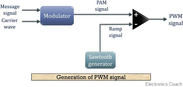
The message signal and the carrier waveform is fed to a modulator which generates PAM signal. This pulse amplitude modulated signal is fed to the non-inverting terminal of the comparator.
A ramp signal generated by the sawtooth generator is fed to the inverting terminal of the comparator.
These two signals are added and compared with the reference voltage of the comparator circuit. The level of the comparator is so adjusted to have the intersection of the reference with the slope of the waveform.
The PWM pulse begins with the leading edge of the ramp signal and the width of the pulse is determined by the comparator circuit.
The width of the PWM signal is proportional to the omitted portion of the ramp signal by the comparator level.
The figure below will help you to understand in a better way how PWM signal is generated by the comparator:
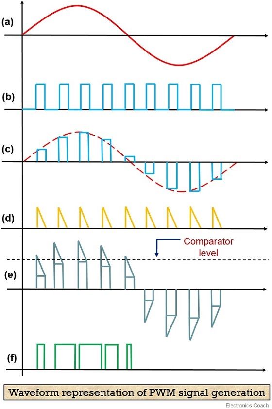
Here, the first image i.e., (a) shows the waveform of the sinusoidal modulating signal and the second one (b) shows the pulsed carrier. After modulation, a PAM signal is generated that is shown in (c). This PAM signal, when added with ramp signal shown in (d), is compared with the reference voltage of the comparator shown in figure (e).
Lastly, figure (f) shows the PWM signal.
We have already mentioned that the width of the pulse is directly dependent on the portion of the waveform that lies above the comparator level.
This is how a pulse width modulated signal is generated.
Detection of PWM signal
The figure below shows the PWM detection circuit, that provides the original message signal from the modulated one.
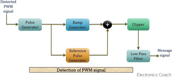
As we know during signal transmission, some noise gets added to the PWM signal. So firstly to remove the noise introduced in the transmitted signal, the incoming signal is fed to a pulse generator. This regenerates the PWM signal.
This regenerated PWM pulse is then given to a reference pulse generator that generates pulses of constant amplitude along with constant width.
The regenerated pulses are also given to the ramp signal generator, that generates a ramp signal of constant slope, whose duration is similar to the pulse duration. Thus we have ramp signal height proportional to the PWM pulse width.
The constant amplitude pulses are then provided to a summation unit in order to get added with the ramp signal. The added output is then fed to a clipper, this clips off the signal up to its threshold value thereby generating a PAM signal at its output.
This PAM signal is then given to an LPF in order to generate the original message signal from the modulated one.
The figure below will provide you with the waveform representation of the process of PWM detection.
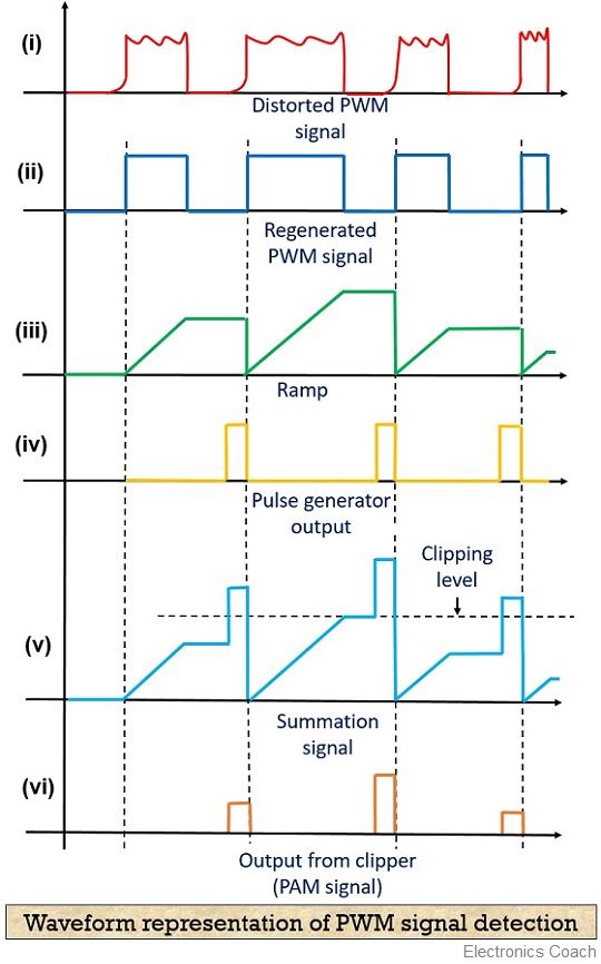
The first image (i) shows the distorted PWM wave and the next one (ii) shows the regenerated PWM pulse.
The operation of the ramp generator is shown in (iii) and (iv) shows the output of the reference pulse generator. The summation operation and clipping off the signal is shown in (v).
The final image of the above figure (vi) represents the PAM pulses from which the original message signal is recovered.
Frequency spectrum of PWM waveform
The spectrum of the PWM signal is shown below
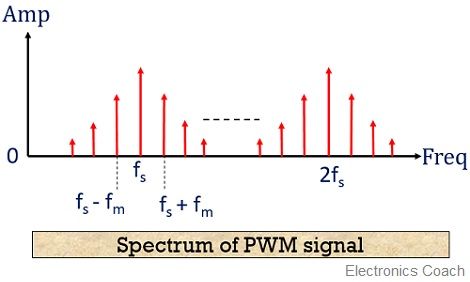
Here, the modulating signal is a sinusoidal signal having frequency fm. Thus the represented spectrum shows the modulating frequency fm along with the several sidebands.
Noise effect on Pulse Duartion Modulation
As we have already discussed that the information content is present in the width of the pulses and not in the amplitude. We also know that noise adds with the amplitude of the pulsed signal causing some variation in it.
Thus, the original information does not get affected by the noise during transmission. Thereby showing immunity towards noise effects.
Advantages of Pulse Width Modulation
- It is more immune to channel induced noise than PAM.
- As noise adds to the amplitude thus the reconstruction of PWM signal from distorted PWM signal is somewhat easy.
- The transmission and reception do not need to be synchronized.
Disadvantages of Pulse Width Modulation
- Due to changing width of the pulses, variation in transmission power is also noticed.
- Bandwidth requirement in case of PWM is somewhat larger than PAM.
Applications of Pulse Width Modulation
It is used in telecommunications, brightness controlling of light or speed controlling of fans etc.
Leave a Reply