Definition: The word ‘static’ corresponds to something which undergoes no change or is fixed and a ‘switch’ is used for the purpose of making or breaking a connection in an electric circuit. The static switch is a device which executes switching operation without the presence of moving parts.
Generally, the power semiconductor devices that hold the ability to get turned ON or OFF within a fraction of microseconds, find application as fast-acting static switches. In low power applications, power transistors are generally used while in high power applications, thyristors are used.
Introduction
Previously in our content on solid-state relay, which is a static switch, we have discussed that mechanical or electromechanical switches were dropped in various applications. The reason for this is, there are some advantages of static switch over electromechanical switches, which are as follows:
- Due to ON time of about 3 microseconds, it offers a high switching speed.
- When turned on, static switches do not exhibit bouncing.
- Due to the absence of moving parts, in static switches, there exist less chances of wear and tear thus reduces maintenance.
- It exhibits long operational life.
A noteworthy point over here is leakage current is an important factor of static switches after it gets turned off.
What are Static Switches?
Static Switches are designed to connect or disconnect the load to or from the supply respectively without the existence of moving parts. In order to actuate an electromechanical switch magnetic coil or plunger is used. While in static switches, Triac or 2 thyristors in an antiparallel arrangement is used.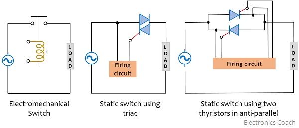
The representation of a static switch with two thyristors in an antiparallel arrangement resembles a single-phase ac voltage controller. However, the way the two operate is different.
In static switches, the semiconductor devices are used for simply connecting or disconnecting the load and the source but these switches have no control over the power delivered to the load. Hence, the power delivered to the load is not changed by the static switches while it is possible with the use of a single-phase voltage controller. Another difference between the two is the semiconductor devices get turned on at the zero-crossing of load current in the case of static switches while in single-phase voltage controllers this is not the case.
Symbol of Static Switch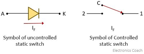
Types of Static Switches
The major classification of static switches is done on the basis of the type of input applied at the terminals.
So, static switches are of two major types:
AC Switches: When the applied input at the terminal of the switching device is ac then these are known as AC switches. Its switching speed is controlled by the frequency of the signal supplied along with the turn off time of thyristors. These can be of a single-phase or three-phase nature.
DC Switches: For the applied input of dc nature at the input terminal of the switching device the switches are known as DC switches. Here the switching speed shows dependency on commutation circuitry as well as turn off time of thyristors.
The designing of static switches is majorly associated with finding the voltage and current ratings of the power semiconductor devices used for its fabrication.
Another classification of switches is done according to their uncontrolled and controlled behavior.
Uncontrolled Static Switch: A diode which is a two-terminal device is regarded as the simplest form of static switch. In an electrical circuit, when an anode is connected to the positive terminal while the cathode is connected to the negative terminal then it is the forward biased condition of the diode. Ideally, the diode conducts when it is forward biased with a negligible amount of voltage drop across it. While in reverse biased condition, no current flows through an ideal diode.
However, in the case of a real diode, in forward biased condition, a small forward voltage drop through the diode, and in a reverse-biased condition, a small leakage current flows through it.
On considering, an ideal power diode, we can say that it acts as an uncontrolled static switch as it gets turned on when forward biased, allowing current to flow through it. However, when reverse biased, no current flows through it, representing the condition of getting off. Thus, here automatic on and off of the diode occurs when forward and reverse current flows through it respectively.
As it is clear that we have only two terminals here and there is no control terminal. Thus, the diode present in the circuit, cannot stop the flow of forward current through it but completely stops the reverse current to flow through it. Hence, we can say, an ideal power diode acts as an uncontrolled static switch that gets on and off according to the polarity of the applied voltage.
Controlled Static Switch: Unlike a diode, a controlled static switch is the one that gets turned on and off by the action of the control circuit. The figure below represents a non-static type of controlled switch where the coil acts as a control element with terminals C1 and C2 which is electrically isolated with the power circuit having terminals 1 and 2.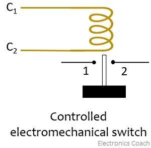
The operation of these non-static type of controlled switches is such that the current flowing through the coil makes it to move and it gets connected with the plunger.
In static power converters, electrical isolation between the control circuit and the power circuit is quite important. According to the electrical signal presented by the control circuit, switching takes place. The control circuits operate in a low voltage power supply and have low voltage electronic components like analog or digital ICs. However, the power terminal of the switch may operate at a high voltage supply with respect to the ground. Along with that, magnitude wise large change in potential is noticed during each switching cycle.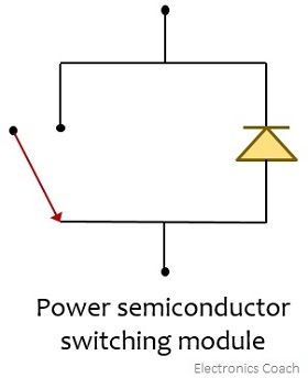
It is to be noted here that there exists no electrical isolation between the power terminal and control terminal in the case of power semiconductor switching devices. Thus, here there is a common terminal for power and control terminals. Hence, all the controlled power semiconductor switches are three-terminal devices. One of the examples of such devices is a power transistor. A power transistor is a three-terminal device namely, emitter, base, and collector. Here emitter and base are the control terminals while the collector and emitter are the power terminals.
In order to turn on the switch, a controlling current is provided to the base and emitter terminal. However, as we have already discussed that there exists no electrical isolation, thus, whenever there is a need for electrical isolation then an electrical isolating device such as a pulse transformer is used. This is basically used to couple the control circuit to the terminal of the switching device.
Applications
The static switches mainly find applications in relays, circuit breakers, UPS, flashers, and fuses. Along with these, they are also used in time delay circuits, transducers, and voltage detection circuits, etc.
Leave a Reply