Definition: Static Induction Thyristor generally abbreviated as SITH is a self-controlled device similar to a gate turn-off thyristor. A SITH has three terminals namely cathode, anode, and gate.
It was developed in the year 1960 by a Japanese engineer and commercially introduced in the year 1988. The commercial use of SITH was promoted by Japanese Universities and Industries.
The key feature possessed by static induction thyristor is that it offers the capability of conducting a large current at a low value of forward voltage and also gets turned off quickly. The figure below represents the symbolic representation of SITH: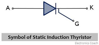
Introduction
A SITH is a semiconductor device that is a part of the static induction device family and is known to be a normally-on device. We know that a thyristor is a bipolar device having 4 layers and 3 terminals that offers a unidirectional flow of current. It is designed to conduct in the on state and block the current in the off state.
A thyristor is not a fully controlled device rather it is a semi-controlled device. This is said because it gets on by the application of gate pulse but to turn it off main supply current must be halted as even after removing the gate pulse, the device continues to conduct. Thus, to overcome this, GTO i.e., gate turn off thyristor was introduced. A GTO is the one that uses the negative gate pulse to turn the device off.
Quick comparison between GTO and Static Induction Thyristor
A static induction thyristor is an advancement of GTO, it operates in a similar way as GTO, however, there are some factors that differentiate a static induction thyristor from the gate turn-off thyristor. The factors are as follows:
- SITH is a device that shows normally-on configuration.
- It gets easily turned off i.e., possesses lower turn-off current gain, usually between 1 to 3.
- A SITH exhibit a higher value of conduction drop.
- It exhibits a higher switching frequency.
- The rate of change of voltage and current with respect to time is high.
- It offers a larger safe operating area.
Structure
We know that a thyristor is a 4-layer device having PNPN layers and as SITH belongs to that family hence it is a p+nn+ diode in which gate electrodes of p+ configuration is buried within the n layer.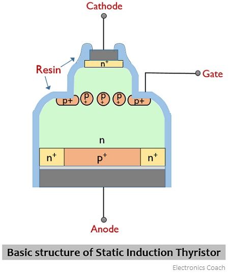
The structural representation of SITH is almost similar to static induction transistor while a small variation in SITH is that a p+ layer exists on the anode side. Along with this, similar to GTO, n+ fingers are diffused in the p+ anode layer.
Working of Static Induction Thyristor
A static induction thyristor is regarded as a normally-on device. In the presence of zero voltage between gate and cathode, the device is in an on state. However, the on-state performance gets improved with a small positive gate voltage. While to turn the device off, necessarily gate reverse voltage is required.
Let us now proceed to understand the turn on and turn off processes of the SITH individually.
Turn-on Mechanism: Consider the simplified structure of SITH shown below for the explanation of the turn-on process of the device: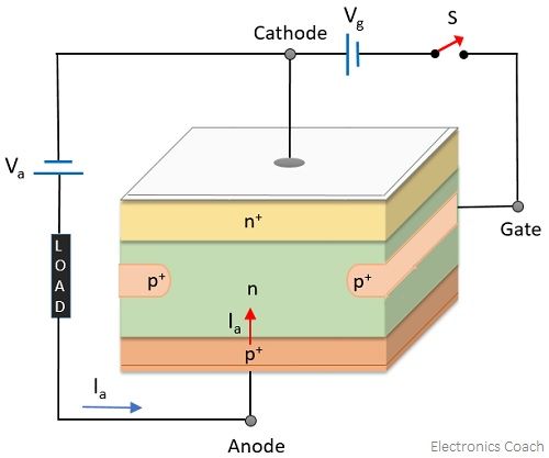
In the forward biased condition of the anode, irrespective of 0 voltage at the gate cathode terminal, the device acts as a diode. Basically, when a positive voltage is applied with respect to cathode then this makes the p+n junction forward biased which leads to cause the flow of load current Ia from anode to cathode.
Hence, it is said that SITH is a normally-on device.
Turn-off Mechanism: Now, consider the structure of SITH represented below to understand the turn-off process of the device: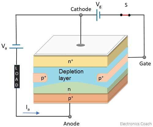
Under the forward biased condition of the anode, when the gate terminal is reverse biased relative to the cathode then it will cause the formation of a depletion layer at the p+n junction. Due to this depletion layer, the anode current now stops flowing from the anode and cathode. With the variation in magnitude of negative potential at the gate terminal, the magnitude of the anode current flowing through the device can also be varied.
In the reverse biased condition of the static induction thyristor i.e., when the cathode is made positive wrt anode then a reverse current from cathode to anode flows. This is due to the flow of electrons from anode intermixed n+ layer, towards the n layer along the p+ grid reaching the cathode after lastly going through the n+ region. This corresponds to no reverse blocking capability of static induction thyristor.
Applications
These mainly find applications in HVDC converters along with in induction heating, and high-frequency power conversion, energy accelerator, and current source inverter.
Leave a Reply