Definition: Thermistors, are the device whose resistance changes rapidly with the corresponding change in temperature. These are highly sensitive to change in temperature, thus widely used in all such applications where temperature measurement is needed.
Thermistor word is composed by the merger of the word thermal and resistor. It can be referred to as transducers as it produces an analog voltage with respective change in temperature.
Let’s have a look at the symbol of thermistor-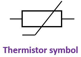
It is a two terminal solid state semiconductor based metal oxides having metallised connecting leads onto a ceramic disc. Its resistance lies in between 0.5 to 0.7Ω. These are widely used in temperature measurement application which ranges from -60﮲C to 15﮲C. As thermistors are highly temperature sensitive device so it makes them extremely useful for precision temperature measurement and compensation.
Constructional details of Thermistors
Two or more semiconductor powder are mixed to form a slurry. This slurry in the form of small drops is formed over the lead wire after which it is dried and put in a sintering furnace.
During sintering, the metallic oxide shrunk onto lead wires and form electrical connections. The beads are then sealed by glass coating. This glass coating improves overall stability. Thermistors can be in the form of discs, beads, rods etc.
The figure below shows some of the different commercial forms:
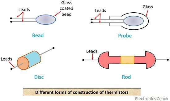
These highly heat sensitive devices are made up of oxides of nickel, cobalt or manganese and sulphides of iron, aluminium or copper.
Smallest thermistor comes in the form of the bead having a diameter in the range of 0.015mm to 1.25nm.
Resistance temperature characteristics of Thermistors
The expression below shows the relationship between resistance and temperature of thermistors
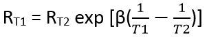
: RT1 = resistance of the thermistor at absolute temperature T1; ﮲K
RT2 = resistance of the thermistor at absolute temperature T2; ﮲K
β = a constant that depends on thermistor material, typically 3500 to 4500 ﮲K
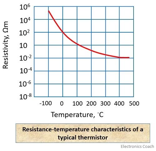
The above characteristics show that a thermistor has a very high negative temperature coefficient of resistance thus makes it an ideal temperature transducer. Platinum is the most commonly used resistance thermometers. Thermistor possesses non-linear characteristics however, a linear range can also be achieved for small temperature range.
For a limited range, the resistance of thermistors is given by –
![]() The sensitivity of thermistors is given by:
The sensitivity of thermistors is given by:
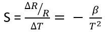
If β = 4000 K and T = 298 K
Sensitivity S = – 0.045 / K
Types of Thermistors
There are mainly two types of thermistors:
- Negative temperature coefficient thermistor
- Positive temperature coefficient thermistor
Negative temperature coefficient thermistors
It is a category of thermistors in which the resistance of the thermistor shows decrement with increment in the temperature. In other words, the value of resistance reduces as the operating temperature increases. Due to their property of causing a significant change in resistance with a small change in temperature, these are widely used for accurate temperature measurement.
These type of thermistor allows a large flow of current if the temperature associated with it increases. Here, the charge carriers that are responsible for the flow of current are generated by the doping process.
When we slightly increase the temperature, the charge carriers collide with the electrons at the valence shell of other atoms. These valence electrons then move freely and collision process is further repeated. This simply means more free electron will cause more current.
Therefore, a small increase in temperature will decrease the resistance of the thermistor due to which large electric current flows. Resistance can vary from a few ohms to several Kilo-ohms.
Positive temperature coefficient thermistors
In this type of thermistor, the resistance rapidly increases with the respective change in temperature. The flow of current reduces the temperature associated with it increases.
The temperature ranges commonly used for switching is from 60﮲C to 120﮲C. These are mostly made from doped polycrystalline ceramic.
Advantages
- Thermistors are compact.
- It provides good stability when aged properly.
- These are inexpensive.
- Only a small temperature variation is needed to have a noticeable change in resistance.
Disadvantages
- It shows non-linear resistance vs temperature characteristics.
- These are not suitable for a wide range of operations.
Applications
- It is used to measure thermal conductivity.
- It is used to measure power at high frequency.
- These are widely used in temperature sensing devices.
- These are widely used to measure flow and level of liquids.
Thermistor exhibits a negative resistance temperature coefficient having a typical value of about 0.05/﮲C.
Leave a Reply