Definition: Cathode ray tube, CRT is the heart of CRO which generates images when electron beam from the back of the tube strikes the fluorescent screen with sufficient energy. CRT technique was basically employed in conventional TV and computer screens.
Constructional details of Cathode Ray Tube
CRT consist of the following parts:
- Electron gun
- Deflection plate assembly
- Glass envelope
- Fluorescent screen
- Base, for connections
The diagram given below shows the internal structure of the CRT
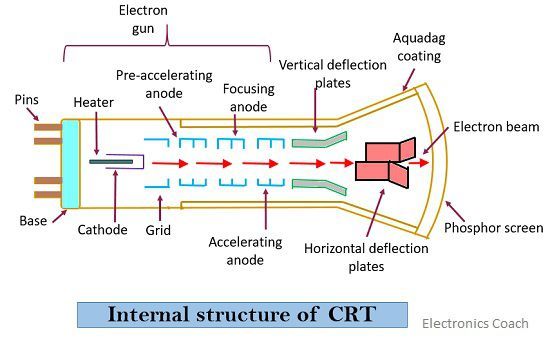
A sharply focused beam is produced by the electron gun assembly. This high-velocity beam strikes the fluorescent screen thus causing a luminous spot on the screen.
The two electrostatic deflection plates deflect the accelerated beam by the application of voltage. This applied voltage enable the beam to move vertically up – down and horizontally from an end to other.
The two movements are not dependent on each other that causes the beam to be arranged anywhere on the screen.
CRT parts are confined in a glass envelope in order to permit free movement of the electron from an end to the other.
Working of Cathode Ray Tube
The main parts of CRT are responsible for the working of it that is explained below-
Electron gun
The electron gun is the originator of focused accelerated electron beam. It consists of a heater, a cathode, pre-accelerating anode, accelerating anode which emits electrons and forms them into a beam.
The cathode is heated indirectly from which electrons are emitted. To obtain high emission of electrons at a moderate temperature a layer of barium and strontium oxide is deposited at the end of the cathode.
An indirectly heated cathode requires current and voltage value 600 mA at 6.3 V. In the case of a highly efficient system the value is 300 mA at 6.3 V.
The emitted electrons further pass through a small hole present in the control grid. The control grid is basically a nickel cylinder of aperture 0.5. It is a low permeability steel material. The intensity by which beam of electron moves depends entirely on the electron emitted from the cathode. The number of electrons emitted from the cathode is controlled by the grid.
A positive high potential is applied at the pre-accelerating anode by which the beam gets accelerated. This high positive potential is about 1500 V. Focusing anode helps in focusing the electron beam and is connected with a lower adjustable voltage of about 500 V.
The highly focused beam moves towards vertical and horizontal deflection plates after which it reaches to fluorescent screen.
Focusing of an electron beam is accomplished by two different methods- Electrostatic focusing and Electromagnetic focusing.
Let us now discuss electrostatic focusing in detail
Electrostatic focusing
In the figure shown below, we can see an electron placed at rest in an electric field produced two parallel plates.
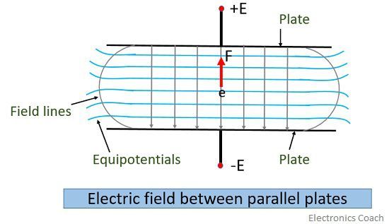
Force on an electron is

Ꜫ = electric field intensity V/m
e = charge of electron
The negative sign indicates that the acting force is opposite to that of the field.
It is necessary that the field is of uniform intensity where the electron is placed. The lateral repulsion of electric field lines causes spreading of spaces between the field lines which results in curved lines at the ends. This is the reason why field intensity is less at the ends.
The force is in opposite direction to that of the field and an equipotential surface is perpendicular to the field thus the force on the electron is in the normal direction to the equipotential surface.
Let us now consider the region of two sides of equipotential surface S as represented in the figure given below-
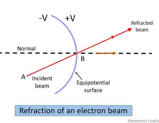
The potential on the left side of the surface is –V and on the right side is +V. Consider an electron is moving from A to B enters on the left side of S. A force is experienced by this electron in the normal direction to the surface S and thus it gets accelerated.
Now, let’s have a look at the functional diagram of the electrostatic focusing arrangement
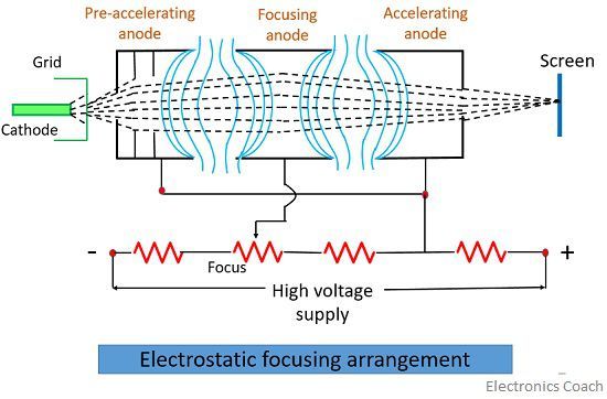
The pre-accelerating anode and accelerating anode are connected to a high positive potential and focusing anode is connected to a lower potential as we have discussed earlier. Due to this difference in potential between focusing anode and accelerating anode a non-uniform field exists on each end of focusing anode. Thus equipotential surface acts as a “double concave lens”.
The beam that enters the field at angles other than normal will be deflected towards the normal and thus causing the beam to be focused towards the centre.
Electrostatic Deflection
The figure below describes the basic arrangement for electrostatic deflection.
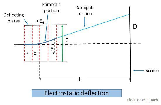
A potential is applied between two parallel plates. A uniform electrostatic field is produced by these plates in the Y direction. Thus the entering electron will experience a force in the y-direction and will be accelerated in that particular direction. There is no force in X and Z directions resulting in no acceleration in these two directions.
After departing from the deflection plates, electrons move in a straight line and sometimes it is hard to deflect a highly accelerated beam called “hard beam”.
Post deflection acceleration
After passing beyond the deflection plates, the electron may and may not experience additional acceleration. But this primarily depends on maximum frequency applied to CRT.
In the electrostatic deflection system, a low value of accelerating voltage must be used and this voltage usually kept below 4 KV. This low value gives better sensitivity but leads to the reduction in brightness. If maximum frequency to be displayed is below 10 MHz generally monoaccelerator tubes may be used.
When the displayed signal frequency is more than 10 MHz, post-deflection acceleration is necessary so as to increase the brightness of the traces.
Deflection Plates
When the electron beam departs from the electron gun, it drifts through 2 pairs of deflection plates.
One pair of plates is mounted in the horizontal direction and produces an electric field in the vertical plane. Thus it generates vertical deflection and is termed as vertical deflection plates or Y plates.
The other pair is mounted in the vertical direction and develops an electric field in the horizontal plane. Thus producing horizontal deflection and is known as horizontal deflection plates or X plates.
The plates are flared so that the beam can pass through it without striking.
Screen for CRT
The front portion of the CRT is the faceplate. It is flat for small screen sizes to about 100mm Χ 100mm dimension and is slightly curved in case of larger displays. Some faceplates are made entirely from fibre optics, having special characteristics.
The inner surface of the faceplate is coated with a phosphor. The electrical energy gets transformed into light energy by the action of phosphor. When an electron beam strikes the phosphor crystal, it raises their energy level.
This is known as cathodoluminescence. During phosphor excitation, light is excited and this is called fluorescence.
To have a flicker-free display, a phosphor must be refreshed by electron before the end of its decay time. Phosphor having lower persistence requires more frequent refreshes. In case of use in radars, long persistence is needed. It is even needed in storage types oscilloscopes. Electron beam on striking phosphor gives off light and heat.
The luminance of phosphor is a measure of its brightness. It is determined by the luminance efficiency of phosphor and by the beam energy.
Aquadag
The electron that strikes the screen, release secondary emission electrons. Aqueous graphite solution known as Aquadag collects these secondary electrons. This aquadag is joined to the secondary anode. To maintain the CRT in electrical equilibrium, it is necessary to collect the secondary electrons.
Leave a Reply