Definition: Distortion in Amplifier basically implies the variation in the waveform received at the output with respect to the applied input. The unwanted alterations generated during amplification is known as distortion.
A pure signal always has a single frequency component where voltage varies positive and negative by an equal amount. If this variation is less than full 360⁰ cycle, then it is said that the signal is distorted.
When we talk about an ideal amplifier, the amplified output must be an exact replica of the input. But practically such an ideal amplifier doesn’t exist. These undesired changes in the signal at the amplifier’s output are basiaclly termed as distortion in amplifier.
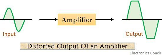
For a distortionless output signal, dc biasing is required at the base or gate terminal. When dc biasing is employed, the signal is amplified over its entire cycle. The bias “Q point” must fall at the middle of the load line.
Thus, with such a “Q point” setting, type A amplification can be achieved. To have a detailed explanation about class A amplifiers refer to our previous article Power Amplifier.
Reasons for signal distortion–
- Due to incorrect biasing when the signal is not amplified for the entire cycle of the input signal then distortion occurs.
- It also occurs in the case when the applied input signal is very large.
- Distortion in amplifier sometimes results when the amplification is not linear over the complete frequency range.
As we are already aware of the fact that the amplifiers basically amplify small voltage signals in order to provide a larger signal at the output. After amplification, the output signal is the value obtained by the multiplication of amplifier’s gain with that of the input signal.
This is the reason why we get an amplified signal at the output of an amplifier. But the gain of amplifier i.e., β is different for the even similar type of transistor. Thus causing variation of “Q point” from a transistor to other.
Types of Distortion in Amplifier
The type of distortion merely depends on the region of characteristics that are used by the transistor, the reactance of the device and the associated circuit.
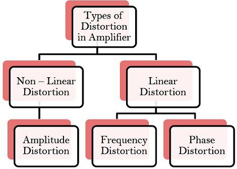
- Non-linear Distortion – This type of distortion occurs in an amplifier when the signal input is large and the active device is driven into a non-linear region of its characteristics.
- Amplitude Distortion:
This type of distortion occurs due to attenuation in the peak value of the waveform. The shift in “Q point” and amplification for less than 360⁰ of the input signal leads to amplitude distortion. It occurs mainly due to incorrect biasing and clipping. As we know that if the biasing point of the transistor is correct, one can have output is the exact replica of input in the amplified form. Let us understand it with the help of the following three cases –- Case 1: Suppose insufficient biasing is provided, the “Q point” will lie near the lower half of the load line. In such condition, negative half of input is clipped and we get a distorted signal at the output of the amplifier.
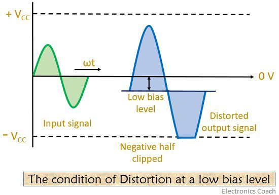
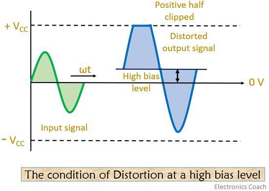
- Case 2: Suppose an extra bias potential is provided, the “Q point” will now be at the upper half of the load line. This condition gives an output that is cut-off at positive half of the waveform.
- Case 3: Sometimes correct biasing also leads to distortion in the output in case of the large input signal. This is so because the large input signal is amplified by the gain of the amplifier. In this case, both positive and negative half of the waveform gets clipped at some portion.
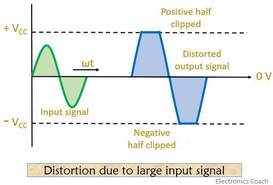 This is also known as clipping distortion. The efficiency of the circuit extremely decreases due to amplitude distortion.
- Case 1: Suppose insufficient biasing is provided, the “Q point” will lie near the lower half of the load line. In such condition, negative half of input is clipped and we get a distorted signal at the output of the amplifier.
- Amplitude Distortion:
- Linear Distortion – This type of distortion occurs when small input signal drives the device and it operates in the linear region of its characteristics. This mainly occurs due to frequency dependent characteristics of the active devices.
- Frequency Distortion:
In frequency distortion, the level of amplification varies with respect to frequency. In a practical amplifier, during amplification input signal consist of fundamental frequency along with different frequency components. This different frequency component is known as harmonics. After amplification, the amplitude of harmonics is somewhat a fraction of fundamental amplitude. Resultantly causing no any severe effect at the output waveform. But if the amplitude of harmonics after amplification goes to a higher value then its effect can’t be avoided as it will be noticeable at the output.The diagram shown below will help you to understand frequency distortion clearly-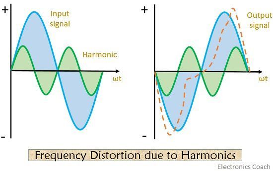
Here the input consists of fundamental frequency along with harmonics. The combination of the two on amplification will give a distorted signal at the output. It occurs either due to the presence of reactive elements or by the electrode capacitances of the amplifier circuits. - Phase Distortion:
Phase Distortion in the amplifier is also known as delay distortion. As the name indicates whenever there is a time delay between input and occurrence of the signal at the output. It is said to be phase distorted signal. It occurs mainly due to electrical reactance. As we have discussed that a signal consists of different frequency components. So, when different frequency suffers different phase shift, phase distortion takes place.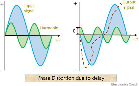 Phase distortion has no practical significance in audio amplifiers as the human ear is insensitive to phase shift. The type and amount of distortion that is tolerable or intolerable depend on the application of amplifier.
- Frequency Distortion:
Generally, the system working gets affected only when the amplifier causes excessive distortion.
SYLVESTER KIPKOECH TANGUS says
Thanks, it was nice