Definition: An electronic device that is used to boost the power level of an input signal is known as an amplifier. Amplifiers are basically used in wireless communication systems that include an analogue signal.
It has the ability to provide an amplified or increased form of an applied input signal.
It is noteworthy that BJT, JFET or MOSFET can be used as an amplifier. However, for amplification, the device must be in the appropriate region. In other words, proper biasing must be provided to the transistor in order to have an amplified signal at the output.
It is a two-port network and holds the following major properties:
- Gain of amplifier
- Input impedance
- Output impedance
Block diagram of amplifier
The figure below shows the block diagram of an amplifier: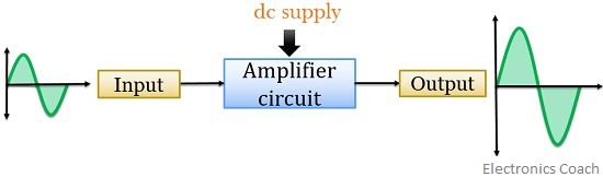
Here, as we can see the transmitted signal is fed to the amplifier as input. The circuitry involved inside the amplifier raises the amplitude of the signal up to the desired level and then further transmits it to the receiver.
The amplifier can be single stage or multistage depending upon the need of the circuit. Sometimes optical signals are also needed to be amplified so in that case optical amplifiers are used.
Two port network of amplifier
The figure below shows the standard amplifier circuit
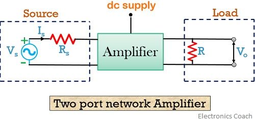
The circuit consists of a practical voltage source and load in order to provide an amplified signal at the output.
As we have already discussed that amplification requires a proper region of operation. So to maintain the device in the proper region, dc supply and various resistors are employed.
1. Gain of amplifier
Gain is defined as the measure of amplification of a signal level. It is a unitless quantity.
For the above circuit the overall voltage gain is given as:![]()
Similarly, the overall current gain is given as:
The power gain of the amplifier is the ratio of output power to the input power but can also be written as a product of voltage gain and current gain.
![]()
2. Input impedance
It is basically defined as the impedance between the input terminal of the circuit. It depends on various factors such as the frequency of the applied signal, gain, feedback etc.
3. Output impedance
The output impedance of the amplifier is shown by the decrease in the voltage level of the signal at the output. It is dependent on current drawn from the output terminal.
Amplifiers are subdivided into various categories
1. Small signal amplifiers or voltage amplifiers
These are basically used for the amplification of small input signal. These amplifiers increase the voltage level of the applied input signal and generate at the output.
2. Large signal amplifiers or Power amplifiers
These are the amplifiers that produce a large signal at the output by converting dc power into ac power. Power transistors are basically employed in power amplifiers.
These are majorly classified as:
Class A: In this class operation, amplified output is achieved for the entire input signal. In order to have a distortionless amplified signal at the output, class A power amplifiers are used. It is sometimes termed as inefficient operation as power conversion from dc to ac at the output is somewhat low.
Class B: Using this class of operation, the output is achieved only for the positive half of the input signal. However, it employs two complementary transistors in which equal but opposite magnitude of the input signal is fed. Therefore, by employing two transistors we can have complete amplified signal at the output.
In this class of operation, a zero crossing error is introduced that is also known as crossover distortion. To have a detailed idea about crossover distortion you can also refer Power amplifiers.
Class AB: A combined operation of class A and B resultantly provides class AB operation. It was basically introduced to overcome the disadvantage of Class B operation. Class AB conducts for more than 180⁰ but less than 360⁰ of the input signal cycle.
Class C: This class is basically used when there is a need to operate at a fixed frequency. It provides output for less than half cycle of input and is highly efficient but is not suitable for audio amplification purposes.
Class D: Class D operation is used for the digital or pulsed input signal. It is highly efficient thus provides good sound quality.
Amplifiers can be used in various forms to have certain applications such as a differential amplifier, operational amplifier etc.
What is a differential amplifier?
A differential amplifier is a type of amplifier that amplifies the difference of the two signals applied to its input. In other words, we can say, it’s a subtractor circuit that subtracts the two applied input and then produces amplified output.
Leave a Reply