Definition: A digital modulation technique in which the amplitude of the carrier wave is altered according to the modulating signal (bitstream) is known as Amplitude Shift Keying (ASK). It is the easiest and straightforward digital modulation scheme.
ASK is sometimes known as On-Off keying because the carrier wave swings between 0 and 1 according to the low and high level of input signal respectively.
Theory of Amplitude Shift Keying
In ASK, frequency and phase of the carrier wave is kept constant and only the amplitude is varied according to the digitized modulating signal. It is also referred as Binary Amplitude Shift Keying (BASK) as its usual operation is associated with only two levels.
However, one can have multiple levels of signal elements also.
In the figure given below, we can see waveforms of amplitude shift keying.
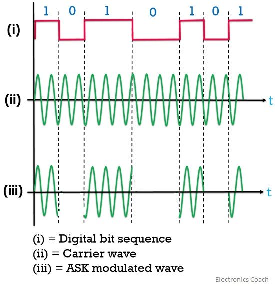
Here, (i) figure represents a message signal represented in the forms of the bitstream, (ii) shows the carrier wave; whose amplitude is to be varied according to the digital message signal.
The last figure (iii) shows the resultant ASK waveform which is amplitude modulated. It is clear from the figure that the signal is present only in case of the high-level digital stream. No signal waveform is achieved when the bit shows a low level, showing on and off behaviour.
Thus, termed as ON-OFF keying.
Generation of ASK signal
The figure below shows the block diagram representing the process of generation of an amplitude shift keying waveform.
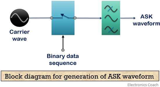
It consists of a signal generator that produces a high-frequency sinusoidal waveform, a message signal in digitized form and a bandpass filter.
The switch provided here gets open and closed according to the bits of the message signal. When the digital bit is of level high i.e., 1 then the switch gets closed. Thus, allows the carrier wave to get transmitted.
As against, in case of low-level bit i.e., 0 the switch gets open and restrict the carrier wave.
This is the reason why the signal appears at the output in case of a high level. After this, pulse reshaping is done by the band limiting filter according to the amplitude and phase characteristics of the filter.
Detection of ASK signal
Detection or demodulation is the process of recovering original message signal from the modulated waveform.
- Coherent detection
It is noteworthy in case of coherent detection that the carrier at the receiver must be in synchronization with the carrier at the transmitter for accurate detection.
The figure below shows the process of coherent detection.
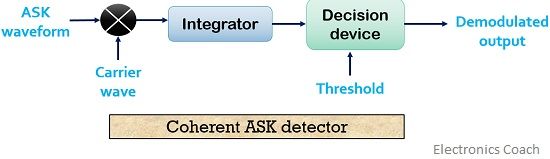
The demodulation circuitry consists of a product modulator along with an integrator and a decision-making device.
Here, the input to the product modulator is modulated waveform along with the sinusoidal carrier. The combination of the two is then fed to the integrator that operates successively according to the bit interval. After which it also executes low pass filtration of the signal.
Then the output of the integrator acts as input to the decision device. Also, a preset threshold is provided to the decision-making device. The decision device compares the signal at its input with the threshold value.
When the signal exceeds the threshold value then bit 1 is provided by the decision device as its output. However, when the signal deceeds (be less than) the threshold value then bit 0 is achieved.
- Non – coherent detection
A coherent detection technique somewhat leads to a complex design as it needs synchronization. However, the design can be simplified by non-coherent detection that makes use of envelope detector.
The figure below shows the block diagram of a non-coherent ASK detection technique composed of a bandpass filter and envelope detector along with a decision device.
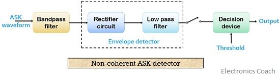
As it does not require a synchronized carrier thus the method makes use of the rectifier circuit for the rectification of the signal. After which the signal is fed to the low pass filter.
The output of which is then provided to a decision device that compares the signal value with the preset threshold value in a similar manner as done in the coherent detection. Thus generates the equivalent output, which is the original digital bit stream.
Note: As ASK is an amplitude modulation scheme, the modulated wave and the message signal has the same bandwidth. Here, an abrupt change in the amplitude is noticed according to the respective change in data bit.
Thus, the scheme allows data transmission in case of low or medium data rate rather than the high data rate.
Advantage of Amplitude shift keying
- Its generation and detection are easy thus facilitate simple transmitter and receiver sections.
Disadvantages of Amplitude shift keying
- ASK technique is not suitable for high bit rate data transmission.
- Poor bandwidth efficiency.
- Highly susceptible to noise and other external factors.
Applications of Amplitude shift keying
- Digital data through an optical fiber is transmitted using ASK technique.
- The technique was widely used in traditional telephone modems.
Thus we can conclude that by using ASK technique, digital data can be transmitted and by varying only the amplitude factor the carrier wave.
ITDesignerspk says
Great content keep it up sis