LED (Light Emitting Diode) is an optoelectronic device which works on the principle of electro-luminance. Electro-luminance is the property of the material to convert electrical energy into light energy and later it radiates this light energy. In the same way, the semiconductor in LED emits light under the influence of electric field.
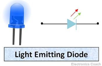
The symbol of LED is formed by merging the symbol of P-N Junction diode and outward arrows. These outward arrows symbolise the light radiated by the light emitting diode.
Now, the question arises how the semiconductor material in LED emits light? The answer to this question lies in the construction and working of LED. The symbol of LED is described in the diagram below, the same symbol is used in electronics circuits.
Construction of LED
The semiconductor material used in LED is Gallium Arsenide (GaAs), Gallium Phosphide (GaP) or Gallium Arsenide Phosphide (GaAsP). Any of the above-mentioned compounds can be used for the construction of LED, but the colour of radiated light changes with the change in material. Below are some of the material and their respective colour of light which they emit. In addition to it, the ranges of typical forward voltage are also given below.
| Materials In Construction | Colour | Forward Voltage (in Volts) |
|---|---|---|
| GaP | Green/Red | 2.2 |
| GaAsP | Yellow | 2.2 |
| GaAsP | Red | 1.8 |
| GaN | White | 4.1 |
| GaN | Blue | 5.0 |
| AllnGaP | Amber | 2.1 |
| AllnGaP | Yellow | 2.1 |
Internal Architecture of LED
The semiconductor layer of P-type is placed above N-type because the charge carrier recombination occurs in p-type. Besides, it is the surface of the device, thus, the light emitted can be easily seen on the surface. If P-type will be placed below the light will be emitted from the surface of P-type but we will not be able to see it. This is the reason that P-type is placed above.
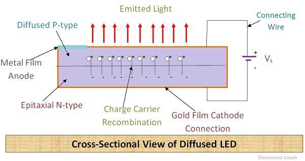
The P-type layer is formed from diffusion of semiconductor material. On the other hand in N-type region, the epitaxial layer is grown on N-type substrate. The metal film is used on the P-type layer to provide anode connection to the diode. Similarly, Gold-film layer is coated on N-type to provide cathode connection.
Significance of Gold-film Layer
The gold-film layer on N-type also provides reflection from the bottom surface of the diode. If any significant part of radiated light tends to hit bottom surface then that will be reflected from the bottom surface to the device top surface. This increases LED’s efficiency.
Working of LED
The electrons are majority carriers in N-type and holes are majority carriers in P-type. The electrons of N-type are in the conduction band and holes of P-type are in the valence band. The energy level of the Conduction band is higher than the energy level of the Valence band. Thus, if electrons tend to recombine with holes they have to lose some part of the energy to fall in lower energy band.
The electrons can lose their energy either in the form of heat or light. The electrons in Silicon and Germanium lose their energy in the form of heat. Thus, they are not used for LEDs as we want semiconductor in which electrons lose their energy in the form of light.
Emission of Photons
Thus, semiconductor compounds such as Gallium Phosphide (Gap), Gallium Arsenide (GaAs), Gallium Arsenide Phosphide (GaAsP) etc. emit light when electrons-holes recombine. The electrons in these compounds lose their energy by emission of photons.
If the semiconductor material is translucent, the light will be emitted from the junction as junction acts as the source of light. LED is operated in forward biased mode only. If it will operate in reverse biased it will get damage as it cannot with stand reverse voltage.
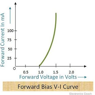
Volt-Ampere Characteristics of LEDs
The characteristics curve of the LED shows that the forward bias of 1 V is sufficient to increase the current exponentially.
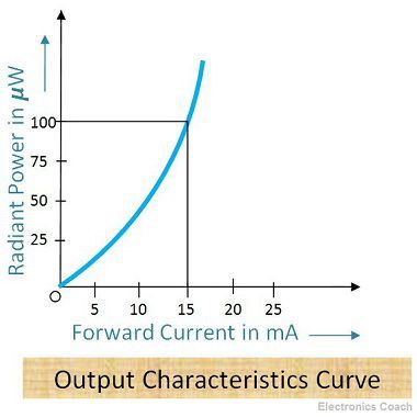
The output characteristics curve shows that radiant power of LED is directly proportional the forward current in LED.
Advantages of LED
- Temperature Range: It can be operated over a wide range of temperature ranging from 00C -700C
- Switching Time: The Switching time of LEDs is in order of 1ns. Thus, they are useful in dynamic operations where a large number of arrays are used.
- Low Power Consumption: They consume less power and they can be used even if the dc power supplied is low.
- Better Controlling: The radiant power of LEDs is the function of the current flowing in it. Thus, the light intensity of LED can be controlled easily.
- Economical and Reliable: LEDs are cheap and they possess a high degree of reliability.
- Small Size and Portability: They are small in size and can be stacked together for the formation of alphanumeric displays.
- Higher Efficiency: The efficiency of LEDs to convert power to light energy is 10-50 times greater than that of the tungsten lamp. The response time of LED is 0.1?S while in the case of tungsten lamp it is in tens or hundreds of milliseconds.
Disadvantages of LED
- Overvoltage or Overcurrent: The LEDs may get damaged when the current is increased beyond a certain limit.
- Overheating due to radiant power: It gets overheated with an excessive increase in radiant power. This may lead to damage of LED.
Applications of LED
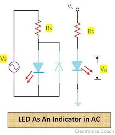
- Indicator in AC circuit: It can be used as an indicator in AC circuit, but the internal resistance of LED is quite small. Thus, a resistor in series is connected with LED so that the overcurrent can flow through the resistor and can protect LED from getting damaged.
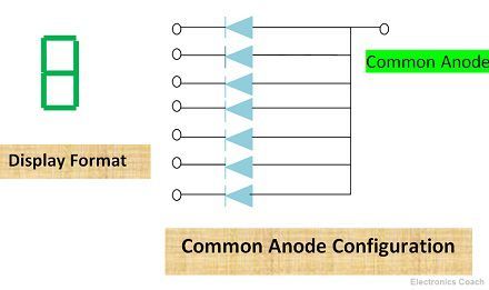
- Display Panel Indicator: LEDs are used for displaying information processed by electronics circuits. The display format of LED is shown in below diagram.
- Digital Watches, Calculators & Multimeters: The LEDs which emit visible light are used in digital watches and Calculators for indication purpose.
- Remote Control Systems & Burglar alarm Systems: Those LEDs which emit invisible infrared light such as GaAs LEDs are used in such applications.
These are the advantages, disadvantages and applications of light emitting diode. LED is a significant optoelectronic device. It is also used in optical fibre communication system.
Leave a Reply