Definition: A Digital Comparator is a combinational logic circuit that is used for comparison of two binary values. Basically it generates the desired signal (either low or high) at the output when compares two digital values provided at its input.
We all know that combinational circuits (like adder and subtractor) produce addition and subtraction of binary values present at the input terminals. But, along with addition and subtraction, some applications require a comparison of two values present at the input terminals.
Majorly a digital comparator is of two types:
- Identity Comparator
- Magnitude Comparator
Here in this section, we will discuss the detailed idea of the digital comparator.
Contents: Digital Comparator
Identity Comparator
A digital comparator that compares only the equality of two applied signals at its inputs is known as identity comparator. It has 2 input and only 1 output pin. The output pin shows a logic high signal when the two values are equal otherwise it shows a low signal.
More specifically, we can say,
For two inputs P and Q, if
P = Q then output HIGH
and if
Magnitude Comparator
Basically a magnitude comparator makes the comparison by considering all the factors. It shows results for either greater, equal or lesser than value by comparing the magnitude of two inputs. Hence contains 3 output pins and accordingly, any one of the 3 output pins of a magnitude comparator becomes high.
Suppose P and Q are the two inputs of magnitude comparator. And the 3 outputs will be P > Q, P = Q and P < Q. And depending upon the comparison performed, any one of the given outputs will be high.
The figure below represents the block diagram of a magnitude comparator having 2 inputs P and Q:

Here in this section, we will separately understand how the output of the comparator changes with the variation in a number of bits at the input of the comparator.
1-bit Magnitude Comparator
Let us first understand the operation of 1-bit binary comparator using truth table:
| P | Q | P > Q | P = Q | P < Q |
|---|---|---|---|---|
| 0 | 0 | 0 | 1 | 0 |
| 0 | 1 | 0 | 0 | 1 |
| 1 | 0 | 1 | 0 | 0 |
| 1 | 1 | 0 | 1 | 0 |
As we can see that for 2 binary input of 1-bit each, we are having 4 possible combinations. And therefore depending on the comparison performed on P and Q, the magnitude comparator makes high any one of the output pins among the three.
It is clear from the truth table shown above that when both the inputs are same i.e., either 0 or 1, then pin 2nd which is showing equivalency between the two value in comparison becomes high.
While when P is greater than Q then the comparator generates a high signal at that respective pin at the output. Similarly, when the magnitude of Q is greater than P then the output at pin showing P < Q will be high.
Let us now see the K-map representation of 2 input Comparator:
For P > Q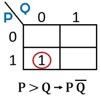
For P = Q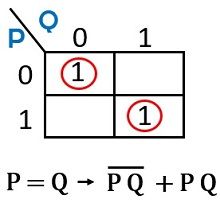
For P < Q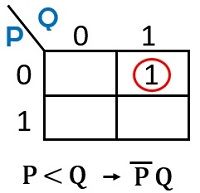
1-bit Magnitude Comparator Circuit
The logic circuit for the 1-bit comparator is given as:
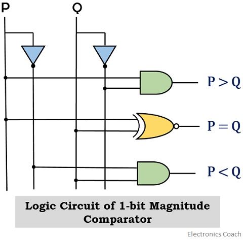
2-bit Magnitude Comparator
For two inputs of 2-bit each, we will have 16 possible combinations. Therefore, in this case, the output will show high and low value depending on the comparison of the 2-bit value of binary input.
Consider the truth table for 2-bit binary comparator:
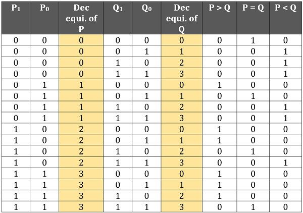
Here we have provided the decimal equivalent of 2-bit binary values for both inputs P and Q in order to have simplicity in comparison.
By observing the table, you can clearly check the different conditions for which the respective output is high.
Like when both the inputs are same either 0 or 1 then the output pin representing P = Q will be high. Similarly, for all those conditions where the bit value of P is greater than Q, then the output pin representing P > Q will be only high.
While when the magnitude of Q is greater than P then the respective pin representing P<Q will be high rest others will be low.
So, in this way comparison between two given inputs is performed by a magnitude comparator.
Let us now see the K-map representation for all the 3 outputs separately:
For P > Q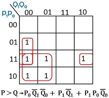
For P = Q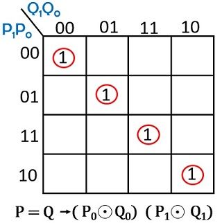
For P < Q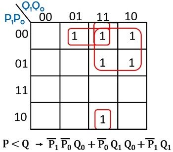
So, on observing the boolean expressions realized from the K-map, we can have the respective logic circuit.
2-bit Magnitude Comparator Circuit
The logic circuit is given as:
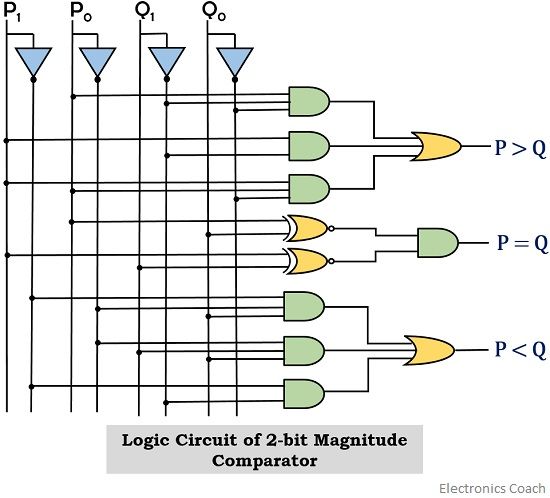
n-bit Magnitude Comparator
Sometimes we come across problems like how to find the number of possible combinations of logic high for P > Q, P < Q or P = Q. And it is not possible all the time that we make a truth table for that particular number of bits and then count the logic high for that respective output.
So we can use a generalized expression for the total combinations of 2 inputs, n-bit each.
As we have 2 inputs of n-bit each therefore in total we have 2n number of bits.
Hence, we will have the possible combinations as:
22n
As seen in the previous section of the 2-bit comparator, there were total 4 (i.e., 22) combinations at the output for which the two inputs were equal (P = Q).
So in the case of n-bit, we can say
P = Q will be total 2n times.
And so P not equals to Q will be 22n – 2n times.
: 22n is the total possible combinations of n bits.
Also, it is to be noted here that the number of combinations where P>Q is equal to P<Q.
Therefore, it can be given as
22n – 2n / 2
: 22n – 2n is the number of logic high value for P ≠ Q.
Suppose we have two inputs of 3-bit each, so in this case
The total number of combinations will be 26 i.e., 64. Therefore, the two inputs will be equal for total 8 times and will not be equal for the rest of the times (i.e., 64 – 8 = 56)
And thus out of 56 combinations, total 28 times 1st input will be greater and for rest 28 combinations the other.
In this way, we can have a comparison for a higher number of bits.
Leave a Reply