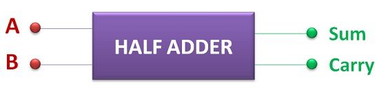
Definition: Half Adder is the digital circuit which can generate the result of the addition of two 1-bit numbers. It consists of two input terminal through which 1-bit numbers can be given for processing. After this, the half adder generates the sum of the numbers and carry if present.
It is very easy to guess the working of the adder just by its name. This is because the word adder consists of keyword “ADD” which means to add any numbers. But what does this keyword “HALF” signifies. You might have confronted this question while going through digital electronics. Let’s discuss what does this mean.
The word “HALF” before the adder signifies that the addition performed by the adder will generate the sum bit and carry bit, but this carry from one operation will not be passed for addition to successive bits. Therefore, it is called half adder.
Although, the major significance of adder is that it can perform addition but apart from this it is also used in processors of computer systems for address decoding. We will also discuss other crucial application later in this article.
Half Adder Circuit
The circuit of half adder can be designed with the help of basic building blocks of digital electronics realm i.e. logic gates. Half adder can also be designed with the help of universal gates. We will discuss all the possible designing one by one in this article.

In the above circuit diagram, it is apparent that one AND gate is used along with EX-OR gate. This is the simplest of all the other possible designs of half adder. The input numbers to be added is given to AND gate as well as EX-OR gate. The AND gate will generate the carry bit as output and the EX-OR gate will generate the sum bit of the addition performed.
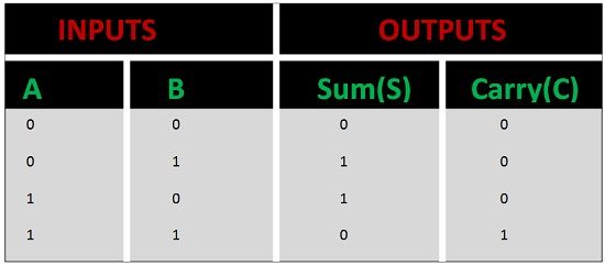
Half Adder Truth table
The truth table of any digital circuit is significant to understand its operations. The truth table consists of all possible combination of input that can be given to the digital circuit and all the resulting outputs.
Half Adder using NAND Gates
The half adder can also be designed with the help of NAND gates. NAND gate is considered as a universal gate. A universal gate can be used for designing of any digital circuitry. It is always simple and efficient to use the minimum number of gates in the designing process of our circuit. The minimum number of NAND gates required to design half adder is 5.
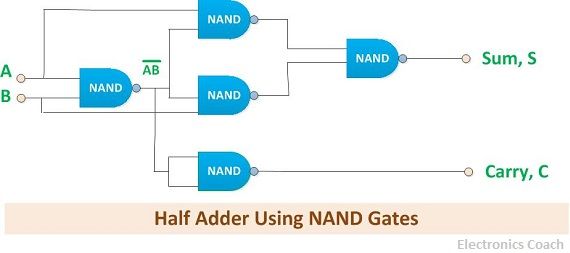
The first NAND gate takes the inputs which are the two 1-bit numbers. The resultant NAND operated inputs will be again given as input to 3- NAND gates along with the original input. Out of these 3 NAND gates, 2-NAND gates will generate the output which will be given as input to the NAND gate connected at the end. The gate connected at the end will generate the sum bit. Out of the 3 considered NAND gates, the third NAND gate will generate the carry bit.
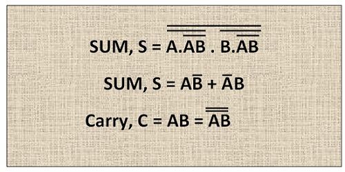
The NAND operation can be understood more clearly with the help of equation given below. These equations are written in the form of operation performed by NAND gates.
Half Adder using NOR Gates
The NOR gate is also a universal gate. Thus, it can also be used for designing of any digital circuit. The Half adder can be designed using 5 NOR gates. This is the minimum number of NOR gates to design half adder.
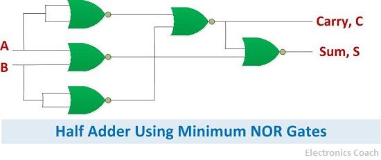
Firstly, three NOR gates are used in the designing and the output from two of these NOR gates is given to fourth NOR gate. The output from second NOR gate is given to the gate connected at the end. This will generate the sum bit of the addition of two 1-bit numbers.
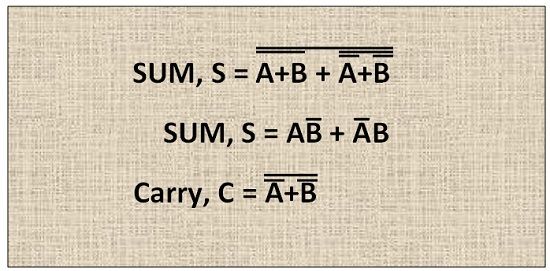
The operation of the above circuit diagram can be understood more clearly with the help of equation. The sum bit and carry bit can be written in terms of NOR operations performed by the logic gates.
Half Adder using basic gates
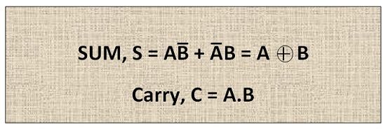
The Half adder can also be constructed using basic gates such as NOT gate, AND gate and OR gate. To understand how to interconnect them so that they constitute Half Adder we should be acquainted with the resulting operation of sum bit and carry bit.
The resulting carry bit of the addition is nothing but the AND operation of both the inputs. And the resultant sum bit is the EX-OR operation of the operands. To design such a circuit which produce the desired result we need 3-AND gates, 2-NOT gates and 1-OR gate.

The NOT gate will negate one of the input and combine with another original input and passes through NAND gates. It must be noted that we need two NOT gate because only one input in negated form will be passed from one NOR gate. To generate the negation of another input we need another NOT gate.
And therefore, the output from two NAND gates will be given as input to the OR gate which will generate the Sum bit of the addition of two 1-bit numbers. And the third AND gate will simply take the two inputs and generate the carry bit of the addition.
Application of Half Adder
Half Adder is used in the arithmetic logic unit of the processor of the computer system for performing arithmetic operations of input. Besides, it is also used in calculators for the addition of number, in address decoding in processors, calculation of table indices etc.
Bhavani guddanti says
Excellent explanation