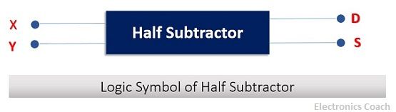
Definition: The Half Subtractor is a digital circuit which processes the subtraction of two 1-bit numbers. In this, the two numbers involved are termed as subtrahend and minuend. In the subtraction procedure, the subtrahend will be subtracted from minuend. The circuit of Half subtractor consists of two inputs and two outputs.
The inputs of the half subtractor circuit will be subtrahend and minuend. On the other hand, the output will be the difference and the borrow.
The word “HALF” before the subtractor signifies that it deals with only two 1-bit numbers, it has nothing to do with the borrow from the previous stage. The logic symbol of half subtractor is represented in the diagram below.
Procedure of Subtraction
We are very familiar with the addition procedure; it is quite easy to add two binary numbers rather than subtracting them. To understand the internal operation of the half subtractor, we must first understand the subtraction rules of binary numbers.
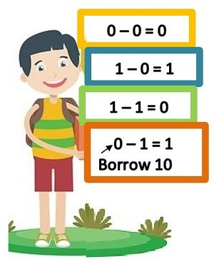
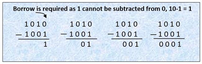
The above image clearly elaborates the subtraction rule of binary numbers. Let’s take an example of subtraction of two multi-bit number with the help of above-defined rules.
Circuit of Half Subtractor
The logic circuit of Half subtractor involves usage of logic gates. In order to design logic circuit, we should understand two concepts. First is the difference operation of half subtractor resembles operation of which logic circuit. Secondly, the borrow generated by half subtractor will also be in accordance with the particular operation which will resemble operation of any logic gate.
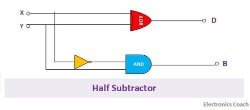
If we observe carefully, it is quite evident that the difference operation performed by half subtractor is exactly similar to the operation of EX-OR gate. Thus, we can easily utilize the EX-OR gate for generating difference bit. Similarly, the borrow generated by half subtractor can be easily obtained by using the combination of NOT gate and AND gate.
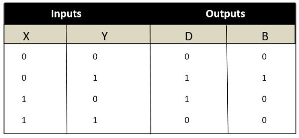
Truth Table of Half Subtractor
The truth table is a key tool to understand the working of any digital circuit. The truth table is nothing but the possible combination of inputs and their resultant output. In case of half subtractor there are two inputs. Thus the number of possible combinations will be 4.
The resultant of all the 4 inputs will be described as outputs. The output of half subtractor is described in two columns. One will signify the difference bit, and another will signify the borrow bit. To derive the truth table, just use the EX-OR operation of two inputs for generating difference and NOT followed by AND operation for generating the borrow bit.
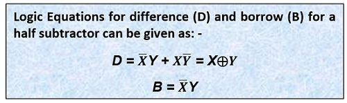
Equation of Half Subtractor
The equation of Half Subtractor can be easily written if we are familiar with the operation of EX-OR gate. The difference equation will be written in terms of EX-OR of two inputs. And the borrow equation can be determined by using the negation operation of the two terminals followed by the AND operation of the two inputs obtained after negation.
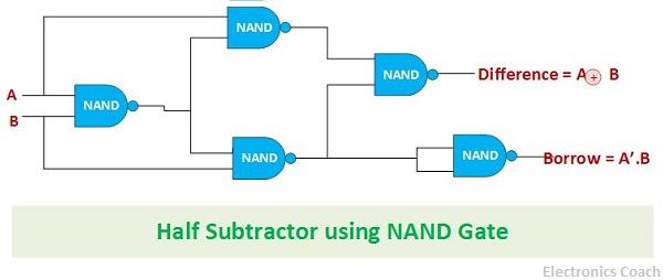
Half Subtractor using NAND gates
The NAND gate is one of the universal gates. It is crucial to have an understanding of universal gate. This is because a universal gate is something which can be used to design any digital circuit. Similarly, NAND gate can also be used to design half subtractor.
The key point which is to be kept in mind while designing the circuit using universal gate is that the architecture in which it is to be connected so that it performs the desired operation. The total of 5 NAND gate are used for designing of Subtractor circuit.
Half Subtractor using NOR gates
The NOR gate is also one of the universal gates. The subtractor can be designed by using 5 NOR gates. The NOR gates are to be connected in such a manner that combination of some of the NOR gates generate the difference bit while the combination of other NOR gate should generate the borrow bit.
The below diagram illustrates the connection of NOR gates to form the Subtractor.

Application of Subtractor
The general thinking which dominates is that subtraction is harder than the addition that is the reason that subtractors are not much popular in comparison to half adders. This is because the subtraction can also be done using addition by using the complement of binary numbers.
Thus, it would not be wrong to say that subtractors are not used extensively. But some of the areas where it finds application is in arithmetic and logic units of processors.
It should be noted that so far we have discussed half subtractor which can be used for subtraction of numbers in the least significant column. For subtraction of multi-bit numbers, subtractor can be used only for the least significant bit. In such cases, we need full subtractor or n-bit subtractor.
Leave a Reply