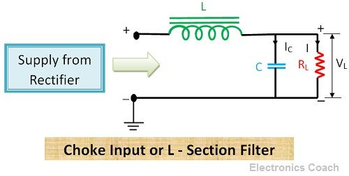
Definition: Choke filter consists of an inductor connected in series with rectifier output circuit and a capacitor connected in parallel with the load resistor. It is also called L-section filter because the inductor and capacitor are connected in the shape of inverted L. The output pulsating DC voltage from a rectifier circuit passes through the inductor or choke coil.
The inductor has low DC resistance and extremely high AC reactance. Thus, ripples get filtered through choke coil. Some of the residual ripples if present in filtered signal from inductor coil will get bypassed through the capacitor. The reason behind this is that capacitor allow AC and block DC.
Significance of Choke Filter or L-section filter
Choke filter came into existence due to shortcomings of the series inductor and shunt capacitor filter. A series inductor filter filters the output current but reduces the output current (RMS value and Peak value) up to a large extent. And the shunt capacitor filter performs filtering efficiently but increases the diode current. The excess of current in a diode may lead to its destruction.
Moreover, the ripple factor of series inductor filter is directly proportional to the load resistance it means as the load resistance increases, ripple factor also starts increasing. And in the case of shunt capacitor, the ripple factor is inversely proportional to the value of load resistance. It implies that in shunt capacitor filter the ripple factor decreases with increase in load resistance and increases with the decrease in load resistance.
Thus, for better performance, we need a filter circuit in which ripple factor is low and do not vary with the variation in load resistance. This can be achieved by using the combination of series inductor filter and shunt capacitor filter. The voltage stabilization property of shunt capacitor filter and current smoothing property of series inductor filter is utilized for the formation of choke filter or L-section filter.
The combination of series inductor filter and shunt capacitor filter is generally used for most of the applications. The combination results in two types, i.e. L-section filter and Pi filter. In this article, we will discuss the working of L-section or choke filter and in next article, we will discuss Pi filter in detail.
Working of Choke Filter or L-section filter
When the pulsating DC signal from the output of the rectifier circuit is feed into choke filter, the AC ripples present in the output DC voltage gets filtered by choke coil. The inductor has the property to block AC and pass DC. This is because DC resistance of an inductor is low and AC impedance of inductor coil is high. Thus, the AC ripples get blocked by inductor coil.
Although the inductor efficiently removes AC ripples, a small percentage of AC ripples is still present in the filtered signal. These ripples are then removed by the capacitor connected in parallel to the load resistor. Now, the DC output signal is free from AC components, and this regulated DC can be used in any application.
If the inductor of high inductive reactance (XL), greater than the capacitive reactance at ripple frequency is used than filtering efficiency gets improved.
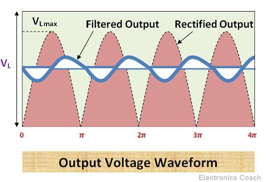
Waveform of Choke Filter or L-section Filter
The waveform of DC output signal with a filter and without filter is shown in the below diagram.
Characteristics of Choke filter or L-section filter
- Regulation: The variation of DC output voltage from rectifier with respect to the DC flowing through load resistor of the rectifier circuit is termed as regulation.
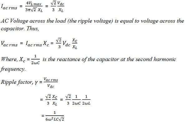
- Ripple factor: This is one of the significant characteristics of the filter. A filter is considered efficient if it can remove ripples effectively. The ripple factor is the ratio of the AC present in the output signal and the DC. More the ripple factor poor will be the performance of the device.
The most effective way to minimize the ripple factor is to increase the value of inductive reactance. The combined reactance of load resistor and capacitor can be minimized up to a large extent by using the capacitor of low reactance so that the complete AC signal get bypassed through the capacitor and regulated DC voltage can be obtained across the load resistor. In these conditions, the net impedance will be due to inductor coil and that will be approximately 2ωL i.e. XL= 2ωL.
- Critical Inductance: The value of inductance can be increased up to a limit and this value of inductance is called critical inductance.
Advantages of Choke Filter or L-section Filter
- It provides better voltage regulation.
- The ripple factor can be varied according to the need.
Disadvantages of Choke Filter or L-Section filter
- Bulky Size: These kinds of filters were popular in ancient time but it has become obsolete now due to bulky size of inductors and capacitors.
- Not suitable for low voltage power Supplies: These are not suitable for low voltage power supplies. IC regulators or active filters are used in such devices.
It is the combination of series inductor filter and shunt capacitor filter. The advantages of both these filters are utilized to form Choke input filters. And the disadvantages of both of these filters are removed in choke filter.
Mati Ullah says
Hi there,
Could you please explain about the critical values of both inductor and capacitor used in the LC filter?
Thank you.