Definition: Inductor is a device which stores energy in the form of magnetic field. When current flows through the inductor, it varies the flux linked with the component. Due to this magnetic field is induced around the inductor and thus the inductor stores energy in the form of magnetic field.
In a circuit, inductor opposes the sudden change of current in magnitude and direction. When current changes suddenly in magnitude or direction, then inductor induces a voltage. The inductor possesses the property to blocks AC and allows DC to pass through it.
If in a circuit there is no sudden change in the current. Then, it offers a high impedance to AC and low resistance to DC.
The wire of any material possess the property of inductance, i.e. possess the property to oppose a sudden change in current. If the wire is coiled in helix shape, the property of inductance will increase equivalent to the square of the number of turns. Inductance is represented by capital letter L, and its measuring unit is Henrys.
Types of Inductors
The wire used in an inductor is made of copper, and it is coiled to achieve various turns to increase its inductance. This copper wire is wounded on either on non-ferrite materials or ferrite materials depending upon the type of the inductor.
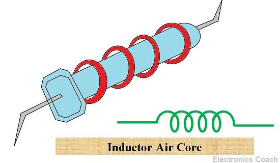
If the copper wire is wounded on the non-ferrite material, it is called Air Core Inductor. The turns of the inductors will vary according to the particular application. A few turns Air Core Inductor possesses the inductance of 0.1 H. It is suitable for the high-frequency application.
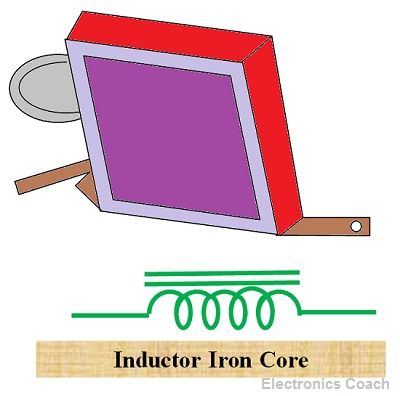
If the wire is wounded on ferrite material, it is called Iron Core Inductor. The iron core inductors of inductance 50 H or more are suitable for low-frequency application.
The inductors can also be classified based on the usage. The various sub-types of inductors based upon the usage are filter chokes or inductor, radio – frequency inductor or choke and an audio-frequency inductor or choke.
Filter Choke or Filter inductors
Filter choke is formed by wounding a wire around the iron core. The iron core is formed by combining laminated sheets in the shape of E and I. The filter choke is widely used in power supplies circuit for removing the AC ripples from pulsating current. The range of inductance of filter chokes is from 1 H to 50 H. The current carrying capacity of filter chokes is 500 mA.
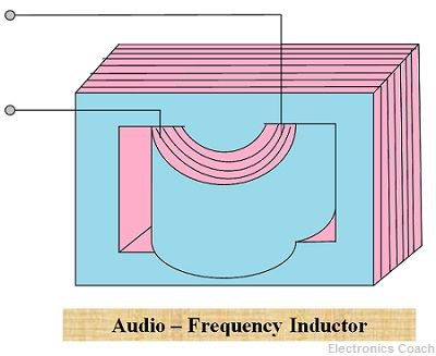
Audio -Frequency Inductors or Audio-Frequency Choke
The audio-frequency chokes are smaller in size as compared to filter chokes. Thus they are suitable for operation at lower frequencies or audio-frequencies. Due to small size, the inductance of audio-frequency chokes is lower than that of filter chokes. This is the reason they are suitable to provide an obstruction to audio-frequencies, i.e. frequencies ranging from 50 kHz to 5KHz.
Radio-Frequency Chokes or Radio-Frequency Inductors
The Radio-Frequency choke is formed by wounding wire on an air core. The number of turns in radio-frequency inductors is more than the audio frequency choke. The inductor thus formed is most suitable for a high-frequency application. The range of radio-frequency inductor varies up to 2mH.
Variable Inductors
In the above topic, we have discussed fixed inductors in which the value of inductance is fixed. In some application, we require variable inductors which possess values which change with the requirement. Such types of the inductors are known as variable inductors.
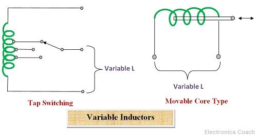
In applications such as phase shifting or tuning circuits, we need to have variable inductors in the circuit. The inductance of the inductor can be varied by changing the number of turns wounded on an iron core. And also by increasing the area of the core inside the turns of wire.
Thus, if we need variable inductors, these two ways mentioned above should be kept in mind.
Colour Coding of Inductors
The value of the inductance of the inductors can be determined with the help of colour coding method. The colour coding procedure of resistors implies here also. If we know the colour coding process of the resistor, we can also determine the inductance of inductors with the help of the same method.
Leave a Reply