Definition: A special type of amplifier that is used to amplify signals of extremely low-level is known as Instrumentation Amplifier. It is basically a differential amplifier, that performs amplification of difference of input signal.
It has high CMMR, offers high input impedance and consumes less power. CMMR stands for common mode rejection ratio, it is the ability to reject unwanted signals.
It is also known as data amplifier. Nowadays, it has become an elemental part of modern testing instruments.
Need of Instrumentation Amplifier
In order to generate quality products, accurate measurement of a physical quantity. Such as temperature, pressure and humidity is the requirement of industrial and control system.
Transducers are the device that is used to measure a physical quantity. It converts one form of energy into another form. Transducer basically transforms the physical quantity into its electrical form. These electrical signals are then used to operate the other units of the system.
However, the transducer generates low-level signals. As these signals do not have the capability to control the other stage of the system. Thus, it is necessary to perform the amplification of such signals.
Also when we talk about long distance signal transmission, then these signals get highly distorted due to noise and atmospheric disturbances.
A normal signal amplifier is not that much suited here. In order to remove noise effects, amplification unit must have a high value of common mode rejection ratio. This is achieved through an instrumentation amplifier.
Instrumentation Amplifier Circuit Design
A 3 op-amp circuit of instrumentation amplifier gives high input impedance in order to have a proper signal measurement from the transducer.
The figure below shows the circuit of a 3 op-amp instrumentation amplifier:
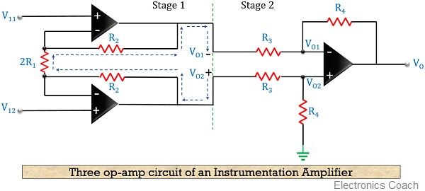
The first stage is nothing but a voltage follower and the second stage is a difference amplifier.
The voltage follower unit consists of 2 buffer amplifier, having high input impedance.
Let us first derive the condition for stage 1:
At the input of the above circuit the current flowing can be represented as:
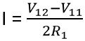
Let, V12 – V11 = Vid
: Vid denotes the input differential voltage
Applying KVL at the first stage of the above circuit,
IR2 + I(2R1) + IR2 = VO2 – VO1
2IR2 + 2IR1 = VO2 – VO1
Substituting the value of I in the above equation,
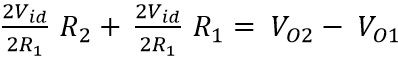
On simplifying we get,
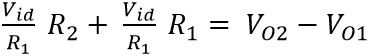
Taking like the term as common, we get,
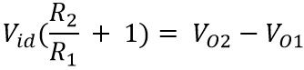
The output of the above-represented circuit is VO, which can be written as
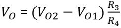
We have recently determined the equation for VO2 – VO1
Substituting its value in the above equation. We get,
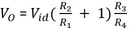
This is the equation for the overall output voltage of an instrumentation amplifier.
Specifications of a good instrumentation amplifier
As recently we have discussed that why do we need an instrumentation amplifier? So, now let us discuss what are the demands of an ideal instrumentation amplifier.
Accurate and stable gain:
As the device amplifies signals of the very low level, thus its basic need is its gain must be finite and accurate. Usually, gain lies in the range of 1 to 100.
Easy gain adjustment:
When we are talking about the gain. Then it is important that it varies properly inside the specified limit. Usually, the gain is adjusted using a potentiometer or by making use of switches like JFET and MOSFET.
High CMMR:
An infinite CMMR is the most preferred range in case of the instrumentation amplifier. As the output of transducer has large common mode noise signals during its long-distance transmission.
An instrumentation amplifier must completely eliminate the common mode noise components in order to amplify the difference of input only.
High input impedance:
It is preferred to have an almost infinite value of input impedance in order to avoid the loading effect at the input.
Low output impedance:
The low value of impedance at the output must be exhibited by the instrumentation amplifier. In ideal cases, it is assumed to be approximately 0 to avoid loading.
Low time and temperature drift:
To have the desired output, it is always recommended that various characteristics and elements of the device must not change with variation in time or temperature.
Low power consumption:
For any device, it is always recommended that it must be power efficient. So, an instrumentation amplifier must also consume less power.
Differential input:
To have the desired amplification, the device must amplify only the difference of the input signal.
High slew rate:
Slew rate provides us with the idea about the change in output voltage with any change in the applied input. So, for an instrumentation amplifier, slew rate must be high.
Advantages of Instrumentation amplifier
- It provides high CMMR.
- Instrumentation amplifier has high input and low output impedance.
- It consumes less power.
Disadvantages of Instrumentation amplifier
- As we know that the device performs amplification of low-level signals that has to be transmitted over long distance. But sometimes originally transmitted signal gets highly distorted due to noise effect because of long distance.
Applications of Instrumentation Amplifier
An instrumentation amplifier can be used both as a temperature controller as well as a temperature indicator. Such amplifiers are used to show variation in the output with the corresponding variation in the temperature.
It also finds applications, in analog weight scaling and light intensity meter. It is also used in controlling current and voltage.
George W says
Thank u