Definition: An astable multivibrator is a type of multivibrator that does not require a triggering pulse thus, sometimes known as a free-running multivibrator. It necessarily provides square wave as its output.
Astable multivibrator is called so because both the states present here are unstable i.e., quasi-stable. This means output swings between 0 and 1 and neither 0 nor 1 is the stable state.
Here, the successive transition is made from one quasi-state to other after some pre-decided time interval.
Circuit and Operation of Astable multivibrator
In this section, we will discuss the operation of an astable multivibrator by collector coupling and by using a complementary pair of transistors. Let us first understand collector coupled astable multivibrator.
1. Collector coupled Astable Multivibrator
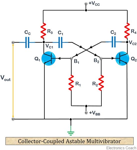
The figure below shows circuit of an astable multivibrator:

The two transistors Q1 and Q2 are employed here which are back to back connected. It is to be noted here that the two transistors cannot be exactly identical. This means, on applying power Vcc both transistors starts conduction.
But, due to variation in operating characteristics, one conducts more than the other.
Let us assume that Q1 conducts more than Q2, so we consider the conduction of Q2 as almost negligible. Hence, considering only Q1 is conducting.
When Q1 starts conducting it starts to move towards saturation region. This causes the collector potential Vc1 at Q1 to become minimum. As we can see in the figure above that collector of Q1 is connected to the base of Q2. So, the low voltage at the collector of Q1 is fed to the base of Q2.
Due to applied low potential, transistor Q2 reaches the cut-off region, thereby causing an open circuit. This causes, a high potential at the collector of Q2 represented by Vc2.
This increased potential as shown in the figure above is supplied at the base of transistor Q1. Thus, causing it to get short circuit by reaching a saturation region.
Hence, the assumption taken at the beginning is satisfied.
After some duration, Q1 completely reaches the saturation region and Q2 at the cut-off region. As we are taking output at the collector of Q1, thus at saturation region Vc is minimum. So, the first unstable state achieved will be 0.
Now, moving further, VBB comes into action, due to which a current start to flow from VBB to Q2. As Q2 is in the cut-off region and behaving as an open circuit. So, the current charges the capacitor C1 connected in the circuit. Thus, producing a voltage across C1.
This high voltage is fed to the base of Q2. Hence causing it to move saturation from the cut-off region by starting conduction. This ultimately reduces the collector voltage at Q2, thereby providing minimum voltage.
This low voltage is then fed to the base of Q1, hence now it moves to the cut-off region. Ultimately, the collector potential at Q1 is increased rapidly.
Hence, the next unstable state achieved is a high voltage i.e., 1.
In this way, the full operating cycle repeats in order to provide a complete square wave at the output. The duration of each of the unstable state is dependent on the time constant. Let us now understand how a complementary transistor astable multivibrator works.
2. Complementary transistor astable multivibrator
An astable multivibrator can also be formed by making use of a complementary pair of transistors. In this case, unlike two transistors astable multivibrator both the transistor either gets on or off at the same time when supply is provided.
As here the power is taken for some short period of time from the supply at the time when the transistor is on. Thus, it consumes very less power as compared to collector coupled astable multivibrator.
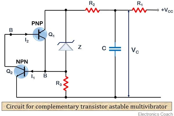
The figure below shows the circuit of a complementary transistor astable multivibrator

As we can see, Q1 is the PNP transistor and Q2 is the NPN transistor.
When power is applied at the circuit, the capacitor in the circuit starts charging up to the applied potential. When the voltage across the capacitor reaches the summation of zener voltage and the cut-in voltage of the transistor, the emitter-base junction of NPN transistor Q2 gets forward biased.
As Q2 starts conduction, now the collector current starts to flow through the emitter-base junction of PNP transistor Q1.
This means that the collector current of transistor Q2 acts as the base current of transistor Q1 denoted by I2. Also, the collector current of Q1 denoted by I1 is the base current of Q2 which can be clearly seen from the figure shown above.
Hence, when the base of Q2 is increased, both the transistor comes to saturation region, causing it to come to on state. Ultimately discharging the capacitor.
When the capacitor discharges, the base current of both the transistors now gets decreased, thus causing the transistors to get off.
The process repeats in order to provide continuous output in case of the astable multivibrator.
Advantages of Astable Multivibrator
- Due to continuous oscillation between 2 unstable states, it is power efficient.
- Its design is simple.
- It is inexpensive.
Disadvantages of Astable Multivibrator
- The feedback provided in case of astable multivibrator does not completely provide entire output to the input.
Applications of Astable multivibrator
These are widely used in radio equipment, in timing circuits and the systems that require square wave as output.
Leave a Reply