Definition: Monostable Multivibrator is a type of multivibrator that has single stable state. MONO means one thus the name itself indicates one state stable and a quasi-stable state. It is also known as a one-shot multivibrator.
Here, a triggering pulse is used in order to have transition from a stable state to quasi-stable state. However, no any triggering pulse is provided to have transition from quasi to a stable state. After a pre-determined time interval, the quasi-state returns automatically to the stable state.
Circuit and Operation of Monostable multivibrator
1. Collector Coupled Monostable Multivibrator
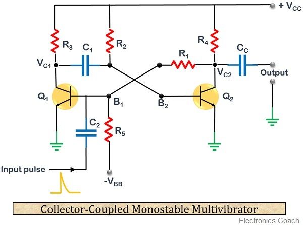
The figure below shows the circuit diagram of a collector coupled monostable multivibrator:

As we can see the circuit is composed of two transistors Q1 and Q2. The circuit is designed in order to have the operation which enables transistor Q2 in conducting state and Q1 in cut off state.
When +Vcc power supply is provided to the circuit, then it forward biases the transistor Q2 through resistor R2. At the same time, –VBB supply reverse biases the transistor Q1 through resistor R5 employed in the circuit.
As we know when a high potential is provided at the base of the transistor then it starts reaching the saturation region. This causes the collector potential of the transistor to get reduced.
Similarly, due to the negative potential applied at the base of the transistor Q1, it starts reaching the cut-off region. This causes the collector potential of transistor Q1 to increase. As the transistor gets completely cut-off, a high potential is achieved at the collector of transistor Q1.
This high potential now charges the capacitor C1 which is placed between the collector of Q1 and base of Q2. So, this potential is then fed to the base of transistor Q2.
Thus it forward biases the transistor Q2. Due to high potential at its base, Q2 starts conduction. This causes the transistor to reach saturation. So, when transistor Q2 reaches saturation completely, then, VC2 becomes very low i.e., almost 0.
As we are taking the output from the collector of transistor Q2 through capacitor CC. Thus, 0 is achieved at the stable state of the circuit.
Now, a triggering pulse of short duration but higher magnitude is applied at the base of Q1 through a capacitor C2. This high magnitude pulse forward biases the transistor and Q1 starts conduction. Due to this now Q1 shifts from the cut-off region to saturation region.
As Q1 reaches saturation, a low potential is achieved at the collector of transistor Q1. Since the capacitor, C1 was charged initially and its charges cannot diminish easily. Thus, the charge on the capacitor is maintained.
The low collector potential of Q1 is now fed to the base of transistor Q2. This low voltage reverse biases the diode and drives Q2 to the cut-off region. Thereby, providing a high voltage at the collector of transistor Q2 which is taken at the output through CC.
It is noteworthy here that this time the achieved state will be quasi-stable. This means that the output will remain high only for the predetermined time duration determined by the time constant of the circuit. After this duration, the output will come back to its stable state.
The high potential at the collector of Q2 is again fed to Q1 and drives it to saturation region. Thus, the process repeats and again a stable state is achieved.
The circuit will now again need a triggering pulse in order to have transition from a stable state to quasi-stable state.
2. Emitter Coupled Monostable Multivibrator
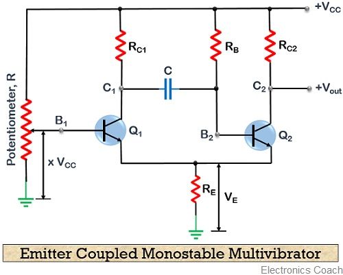
The figure below shows the circuit diagram of an emitter coupled monostable multivibrator:

Here, also we have formed the circuit that operates with Q2 as conducting and Q1 in a non-conducting state.
As Q2 is in its conducting state, the large voltage drop across RE provides a negative voltage to the base of transistor Q1. The potentiometer employed in the circuit now forward biases the transistor Q1. Due to this now Q1 starts conducting.
As forward bias drives Q1 to saturation, the collector voltage of transistor Q1 drops. This low voltage is then fed to the base of transistor Q2 through capacitor C in the circuit. This low voltage drives Q2 to cut-off, due to which voltage drop across RE reaches the minimum.
This resultantly causes more current to flow through the transistor. Thus, low potential at the collector of Q1 drives Q2 to cut-off. By passing time, the capacitor is charged by the current flowing through the circuit.
Due to the stored charge at the capacitor, a high voltage is provided at the base of Q2. This again causes Q2 to start conduction.
As Q2 conducts, the voltage drop across RE also rises, resultantly causing Q1 reverse bias. The process is further repeated in a similar way.
In the end, we achieve, Q1 in cut-off and Q2 in the saturation region. Thus the original stable state is achieved from quasi-stable.
This is how a monostable multivibrator works.
Advantages of Monostable Multivibrator
- These are inexpensive.
- The circuit design is simple.
Disadvantages of Monostable Multivibrator
- To provide sufficient charging and discharging time to the capacitor. The time to apply the upcoming trigger pulse must be more than the predetermined time constant.
Applications of Monostable multivibrator
A monostable multivibrator is basically used in the regeneration of a distorted pulse. It provides a sharp pulse from a distorted pulse. Also, the output of the monostable multivibrator is used to trigger any other pulse generator circuit.
Leave a Reply