Definition: A type of multivibrator whose output consists of 2 stable states is known as Bistable Multivibrator. The circuit switches from one stable state to the other when an appropriate trigger pulse is applied.
In a nutshell, in a bistable multivibrator, one stable state can be maintained until a triggering pulse is provided.
It is also known as flip-flop multivibrator because due to applied trigger pulses, multivibrator flip from one stable state. And by applying the next trigger pulse it flops back to its initial stable state.
Circuit and Operation of Bistable Multivibrator
The figure below shows the circuit of a fixed bias bistable multivibrator:
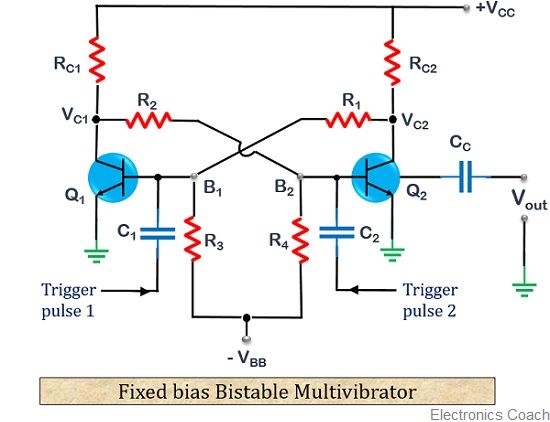
In fixed-bias bistable multivibrators, the device is biased by using two different sources. The circuit comprises of 2 identical transistors namely, Q1 and Q2. And the output of each is given as input to the other.
The resistors R1 and R2 are the part of the feedback network. Here, the two collector resistances RC1 and RC2 are equal.
Let us now move further and understand the working of a bistable multivibrator.
- As the power supply is provided both the transistors come into conducting state. As we know that no two transistors are exactly equivalent and show some variation in their operating principle. Thus, one of the transistors conducts more than the other.
Let us consider that here Q1 conducts somewhat more than Q2. Hence for simplicity, we assume that Q1 is conducting and Q2 almost negligibly conducting.
As Q1 is conducting, thus its collector potential start dropping. This low potential is fed to the base of transistor Q2 through resistor R2. Due to the applied low voltage, the conducting state of Q2 drops. This causes the collector potential of transistor Q2 to increase.
This increased potential is then fed to the base of transistor Q1 through resistor R1. This potential puts the transistor in a more forward biased condition. Due to this cumulative action, Q1 reaches saturation and Q2 reaches cutoff.
The collector potential of saturated transistor Q1 becomes nearly 0 and the collector potential of cut-off transistor Q2 reaches the maximum value of the supply voltage i.e., VCC.
As we are taking the output from the collector of transistor Q2 through CC. Hence, the first stable state achieved is 1.
- Now, consider a negative trigger pulse of high magnitude and short duration is provided to the base of transistor Q2 through a capacitor C1. This trigger pulse causes a reduction in the forward biasing provided to the transistor Q1. Due to this, Q1 now conducts less than the previous case.
This leads to an increase in the collector potential of transistor Q1. This increased voltage is then provided to the base of transistor Q2. That causes Q2 to conduct more than earlier. Thus, a low voltage is achieved at the collector of transistor Q2.
This low voltage is fed back to the base of transistor Q1. This causes it to conduct less thus generating a high potential at the collector of transistor Q1. This successive cycle drives Q1 to cutoff and Q2 to saturation. Thereby, generating a low voltage at the collector of transistor Q2. So, now 0 is achieved at the output due to saturated transistor Q2.
Hence, we get 0 as the next stable state of the bistable multivibrator.
In order to have transition from current stable state to the next stable state, another triggering pulse is required to provide.
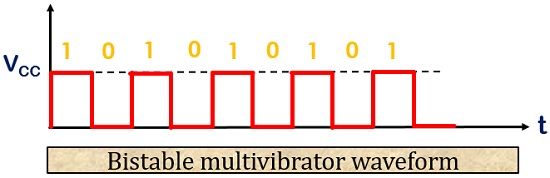
The output of the bistable multivibrator is shown below:
It is to be noted here that, the maximal collector current is achieved in case of saturation condition. So, in order to limit this current RC1 and RC2 must be chosen accordingly.
Also, the value of four resistances R1, R2, R3 and R4 must be larger than RC1 and RC2. This is done to eliminate loading effects.
Loading in Bistable Multivibrator
As bistable multivibrators are used to drive other circuits. Thus, shunting loads must be present at one or both the collectors of the transistors. These loads decrease the collector potential of the cut-off transistor.
Due to this, the voltage at the output will show less swing.
The loading in bistable multivibrator varies according to the application. This causes variation in the saturation level of the transistor.
Advantages of Bistable Multivibrator
- It has the ability to store previous output until no any input trigger is provided.
- The circuit design is not complex.
Disadvantages of Bistable Multivibrator
- Every time in order to have transition from one stable state to another, triggering pulse is required.
- It is somewhat costly than astable and monostable multivibrator.
Applications of Bistable Multivibrator
These are widely used in the circuits of latches and counters. It is also used in frequency divider circuits and in storage devices.
Leave a Reply