Definition: Asynchronous counters are those counters which do not operate on simultaneous clocking. In asynchronous counter, only the first flip-flop is externally clocked using clock pulse while the clock input for the successive flip-flops will be the output from a previous flip-flop.
This means that only a single clock pulse is not driving all the flip-flops in the arrangement of the counter.
Asynchronous counters are also known as ripple counters and are formed by the successive combination of trailing edge-triggered flip-flops. It is called so because the data ripples between the output of one flip-flop to the input of the next.
Before knowing about asynchronous counter one must know what are counters? So let us first understand the basic idea of counters.
What are Counters?
Counters are one of the most useful parts of a digital system. A counter is a sequential circuit that holds the ability to count the number of clock pulses provided at its input.
The output of the counter shows a particular sequence of states. This is so because in the applied clock input the intervals of the pulses are known and fixed. Thus can be used to determine the time and hence the frequency of the occurrence.
An arrangement of a group of flip-flops in a predetermined manner forms a binary counter. The applied clock pulses are counted by the counter.
We know that a flip-flop has two possible states, therefore for n flip-flops there will be 2n number of states and permits counting from 0 to 2n – 1.
Counter are of two types – Asynchronous and Synchronous Counters.
Here in this section, we will discuss asynchronous counters.
Circuit and Operation of Asynchronous Counter
The figure given below shows the circuit diagram of a 3-bit asynchronous counter:
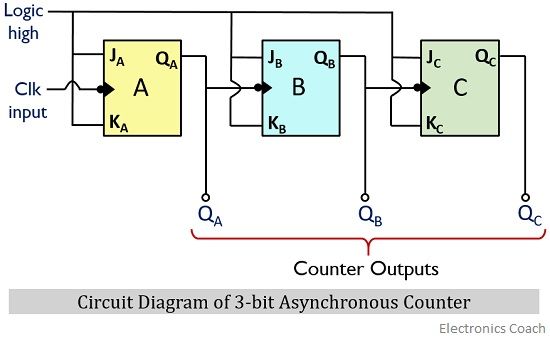 Here as we can clearly see that 3 negative edge-triggered flip-flops are sequentially connected where the output of one flip-flop is provided as the input to the next. The input clock pulse is applied at the least significant or the first most flip-flop in the arrangement.
Also, logic high signal i.e., 1 is provided at the J and K input terminals of the flip-flops. Therefore, the toggling will be achieved at the negative transition of the applied clock input.
Let us now have a look at the timing diagram of the 3-bit asynchronous counter:
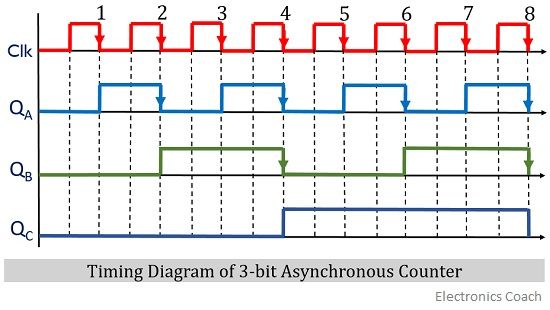 Initially when the clock input is applied at the LSB flip-flop i.e., A then the output QA will change from 0 to 1 at the falling edge of the clock pulse. As we can see that at the first count of a clock pulse at the falling edge, QA toggles from 0 to 1.
Further QA holds its state 1 and toggles from 1 to 0 only when another falling edge of the clock input is received. Again QA toggles from 0 to 1 at the next falling edge of the input clock pulse.
As we have already discussed that only the first flip-flop is triggered with an external clock signal. So, now the output of flip-flop A will act as the clock input for flip-flop B and the external clock signal will not be going to affect QB.
Therefore, the further toggling of the QB will depend on the falling edge of QA signal.
So, as we can see clearly in the timing diagram that QB undergoes toggling only at the falling edge of the QA signal. And the clock input signal is not affecting the output of flip-flop B.
Further for flip-flop C, the clock input will now be the output of flip-flop B i.e., QB. So, the output QC will be according to the transition of QB.
As we can see in the diagram that first time QC toggles from 0 to 1 only at the first falling edge of QB signal. And maintains the state till it reaches the next falling edge of QB.
So, in this way, we can say that we are not simultaneously providing a clock input to all the flip-flops in asynchronous counters.
Now the question arises by this how the counter counts the number of states?
Basically, the number of states depends on the number of flip-flops employed in the circuit.
A 3 flip-flop arrangement counter can count the states up to 23 – 1 i.e., 8-1 = 7. Let’s understand this by the help of the truth table given below:
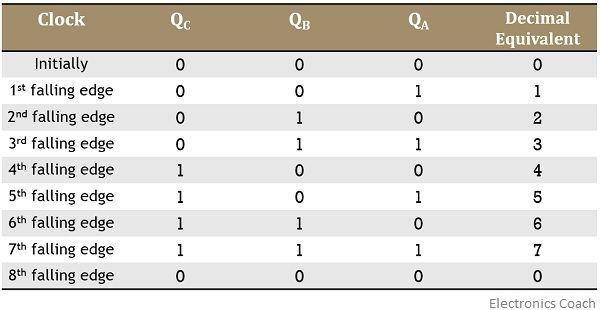
As we can see that initially, the outputs of all the 3 flip-flop is 0. But as we move further then we see that at the first falling edge of the clock input, QA is 1 while QB and QC are 0, thereby providing decimal equivalent as 0. Again for the second falling edge of the clock input QB is 1 whereas QA and QC are 0, giving a decimal count 1.
Similarly, for the 3rd falling edge, QA and QB are 1 and QC is still 0. In the case of 4th falling edge, only QC is 1 while both QA and QB are 0 and so on.
In this way, we can draw the truth table by observing the timing diagram of the counters. And the truth table provides the count of the applied input clock pulse.
Thus, we can say an asynchronous counter counts the binary value according to the clock input applied at the least signal bit flip-flop of the arrangement.
A 3-bit counter is also known as mod 8 counter due to the presence of 8 states.
Applications of Asynchronous Counter
These are used in applications where low power consumption is required. And are also used in frequency divider circuits, ring and Johnson counters.
Leave a Reply