Definition: The type of filters that are designed to block or highly attenuate a specific band of frequencies is known band stop filter. It is sometimes known as band reject or band eliminate filter. A more common name for these filters is Notch Filter. It is a second-order filter that has two cut-off frequencies.
Band reject filters are formed by utilizing the characteristics of high pass and low pass filters.
What are Filters in Electronics?
Filters serve as crucial components of the communication system as during signal transmission there exists a requirement to eliminate the unwanted frequency components and boost a particular range that is required.
Filters are basically frequency selective circuits that are designed to select a specific frequency range that can be passed or blocked depending on the requirement. There exist various practical applications of filters like in stereo systems where the audio frequencies are required to be amplified or suppressed, in equalizers for amplitude adjustment of various frequencies, in crossover networks where frequencies are blocked towards the speaker’s end, etc.
Filters are classified as:
Low pass filters are designed to pass the frequency components less than a cut-off frequency and block higher than that frequency.
High pass filters are those filters that operate opposite to low pass filter and simply rejects or attenuates the signal below the cut off frequency and passes the one that falls above the cut off frequency.
Band pass filters are the filters that allow a particular band of frequency to pass through it and rejects the one falling out of that particular band. It has two cut-off frequencies that signify the specific band to be passed.
Other than these three another type of electronic filter exists known as band stop filter which we are going to discuss in this article.
Introduction to Band Stop Filter
Band Stop filters are the one that performs opposite operation to that of band pass filters. As the name itself is indicating that it is a type of filter that rejects or highly attenuates a particular band of frequencies and passes all the components existing out of that specific band.
While a band pass filter does completely reverse operation passing the frequency existing within the band and rejecting the components present out of it.
We have discussed in our previous content on band pass filter that it can be formed by serially combining low pass and high pass filters. So, a band reject filter can also be formed by the combination of low pass and high pass filters but this time they must be arranged parallelly rather than serially.
Band stop filters are generally classified as:
- Wide band stop filter
- Narrow band stop filters
The narrow band-reject filters are sometimes referred to as notch filters due to the fact that these possess high-value quality factor i.e., Q more than 10 where the bandwidth is very small in comparison to wide band reject filters.
We know that a band of frequency has two cut-off frequencies signifying lower cut-off frequency and higher cut-off frequency. So, the band existing between the two cut-off frequencies is blocked by a band stop filter and the rest other frequency components easily get passed through it. Thus, is known to be a complement of BPF. Hence, we can say, a band reject filter has two pass bands and one stop band.
To understand this in a better way suppose ω1 and ω2 are the two cut-off frequencies and the ideal response is shown below: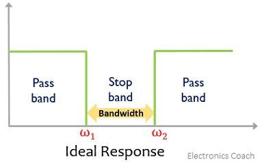
Here the two pass bands are 0 to ω1 and ω2 to ω while the stop band is ω1 to ω2. However, the practical response of band stop filter is shown here with center frequency ω0 corresponding to the least amount of gain i.e., almost zero.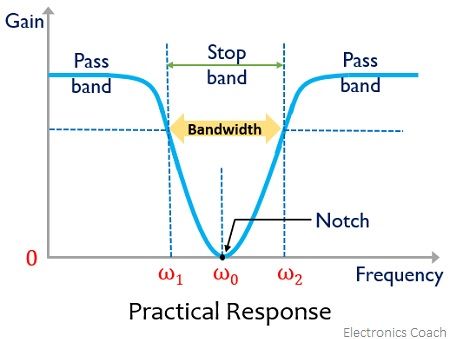
The practical response clearly shows a notch at the center frequency.
Band Stop Filter Circuit
Wide Band Stop Filter
The figure below represents the circuit diagram of the wide band reject filter: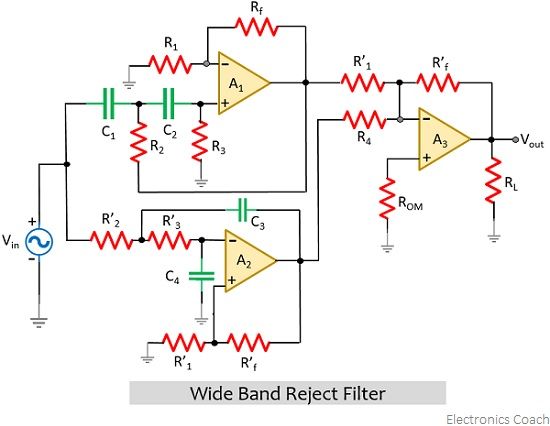
Here, by using the op-amp in the design, voltage gain is introduced in the filter circuit. Basically here a low pass filter, a high pass filter, and a summing amplifier is used. To have the accurate band reject response, the designing must be done in a way that, low cut-off frequency of high pass filter fL must exceed the high cut-off frequency of low pass filter fH. Along with that the high pass and low pass filters must have equal passband gain. This is so because only by this, a proper stop band can be achieved.
The figure given below shows the practically achieved frequency response curve of the band reject filter: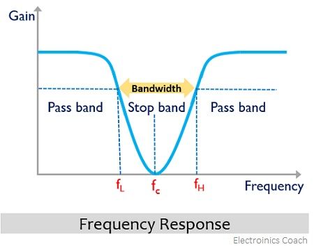
Narrow Band Stop Filter
The figure represented below shows the narrow band stop filter circuit: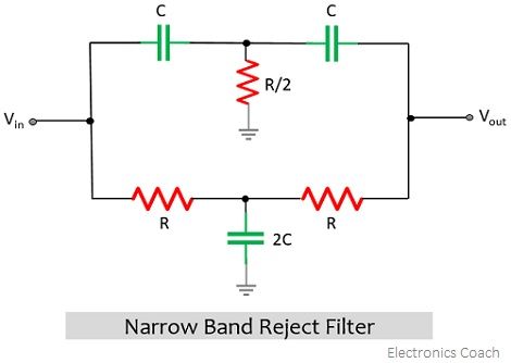
The notch filter given here is formed of two T-shaped networks (also known as twin T-network). It is clearly represented in the figure given above that one T network is formed by the combination of two resistors and one capacitor while the second T network is formed by combining two capacitors and one resistor.
- You must note here that the capacitors in the above design are in such configuration that the upper two capacitors are C while the capacitor in the middle of the network is 2C. Similarly, the two resistors at the bottom are R but the one present in the middle is R/2. To have the proper narrow band reject operation this described configuration must always be maintained.
With the use of notch filters, even a single frequency or a very small band of frequencies can be highly attenuated without attenuation of wide bandwidth constituting of different frequency components. The most common application of these filters includes eliminating single frequency such as 50 Hz power line frequency generating hum (i.e., electrical noise).
The equation for twin T notch filter is given as:![]()
A noteworthy point over here is that the passive twin T network described above offers a crucial disadvantage where the value of Q is quite low. But drawback can be overcome by the addition of a voltage follower circuit as shown below: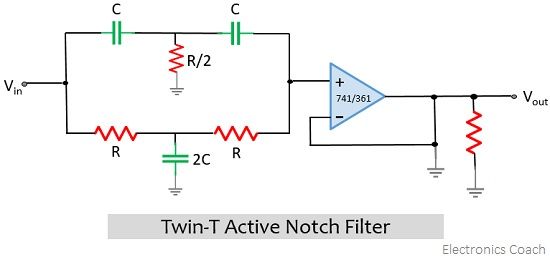
Here the output of the voltage follower circuit is fed back to the 2C and R/2 junction.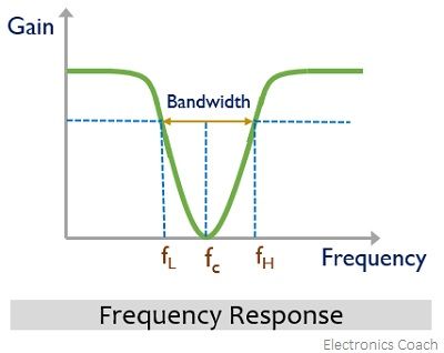
Applications
As band stop filter removes the unwanted frequency component thus used in communications and medical applications such as biomedical instruments. These are used in telephone line services to reduce the chances of noise during signal transmission. Also to suppress noise these are used in image and signal processing.
To have audio of better quality these filters are used in public address and speaker systems. Also, in optical communications, optical fiber cables are used in which while transmitting light signals distortions occur and these distortions can be easily removed by the use of band stop filters.
Leave a Reply