Dielectric Heating is a process of electric heating by which the temperature of a dielectric (non-conducting) material is raised by the application of an alternating electric field (high voltage ac signal). The increase in temperature results in heating the substance which is in contact with the external field.
Dielectric heating is sometimes called high frequency or radio-frequency heating, capacitive heating. This process allows uniform heating of non-metallic materials which are unable to conduct electricity.
Introduction
Whenever we hear the word ‘fire’ then the first thing that we understand from it is something related to ‘heating’. So, basically, the fire was one of the major elements that was used in earlier days by human beings for purposes like cooking food, moulding, or welding of metals, etc.
However, with various technological advancements in recent years, so many alternatives have come into existence to perform such applications without the need for fire. Dielectric Heating is one of the valuable inventions relative to this field as through this a new way has evolved for such processes without the involvement of fire.
What is dielectric?
Dielectrics are basically insulators that possess very poor conducting ability relative to electric current. We know that every matter in this universe is composed of molecules whose elemental particle is an atom.
When an external field is not present then the polar molecules within a material are randomly positioned within it. However, by applying an electric field, the material gets polarized, this is because the dipole moments of polar molecules get properly oriented. Now the question arises – how this happens?
Basically, in conductors, the loosely bounded electrons drift through the material when it is connected to the external electric field. However, this is not the case with dielectrics as they do not have loosely bounded electrons or free electrons for such actions. But here dielectric polarization occurs.
Dielectric Polarization is nothing but the presence of polar molecules in the proper orientation. To understand this, consider the figure shown below: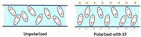
Here there are two conductive plates separated by dielectric material in both images.
The first one is unpolarized due to the absence of an electric field. However, in the second figure, it is seen that the arrangement is subjected to an electric field because of which there is a slight displacement of positive charges in the direction of the electric field and negative charges in the opposite direction of it.
The minute charge separation within the dielectric is known as polarization and this leads to a reduction in the electric field within the dielectric.
Operating Principle of Dielectric Heating
The principle of operation of a dielectric heater is such that a non-conducting material is present between two electrodes and an external electric field is applied across these two electrodes. Basically, a wide range of frequency is provided to the electrodes.
- It is to be noted here that radio-frequency radiation is a form of energy and not a form of heat. So, it requires material matter for the conversion of heat from energy.
The dielectric material which is present between the two electrodes can be anything such as wood, plastic, glass, etc. Though it is considered that a dielectric does not allow the flow of electric current through it, practically, it is not possible.
So, whenever these materials are provided with a high voltage alternating supply then even minute motion of charged particles results in the flow of current which leads to dielectric losses. This resultantly produces heat within the material.
Circuit Operation of Dielectric Heating
Till now we have got the idea that the sole purpose of a dielectric heater is to heat up an insulating material. A dielectric heater is regarded as an electric heater as it transforms electrical energy into heat.
We have already discussed induction heating (which is also a type of electric heating) in our previous content where the principle of electromagnetic induction is used to heat up the magnetic material without making direct contact with the source.
The figure below shows the circuit arrangement of a dielectric heater which is formed by encapsulating an insulating material between two conducting plates forming a parallel plate capacitor arrangement.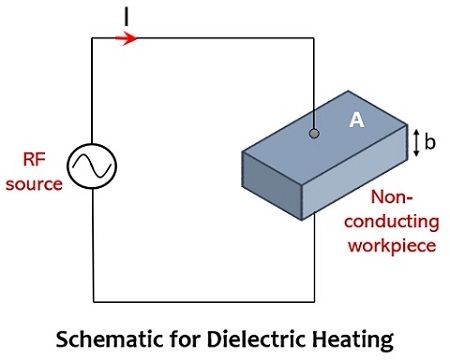
Here a very high-frequency ac voltage signal i.e., 20KV with frequency ranging between 10 to 50 MHz is provided across the whole capacitive arrangement.
We have already discussed that dielectric loss results in the generation of heat. Now, the question arises – when this dielectric loss becomes this much significant that it heats up the insulator?
So, generally, when sinusoidal voltage is provided to the capacitor shown above then the capacitor draws some current. However, this current never leads the voltage by exactly 90°. This means that there exists some in-phase relationship between the supplied voltage and the flowing current. This resultantly produces power loss within the dielectric of the capacitive plates.
At the ordinary frequency range of 50 Hz, this loss is not that significant that it can cause heat generation and so can be neglected. However, at larger frequencies i.e., in the megahertz range, the loss becomes quite large and this heats up the dielectric. This property of the whole configuration is utilized for the purpose of heating the dielectrics (insulating materials).
- It is to be noted here that the amount of dielectric loss produced depends on the supply voltage and frequency. Therefore, in order to get the high heating effect, one must need to provide a very high-frequency voltage signal as this will give rise to high dielectric loss and so high heating effect.
The equivalent circuit and the phasor for the above-shown schematic are given below: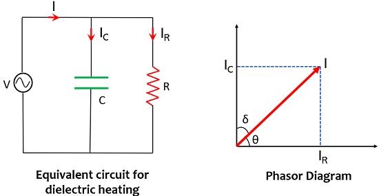
The power dissipated within the dielectric material will be given as:![]()
Since,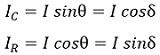
Thus,![]()
And substituting the value of I from IC = I sinθ in the above equation, we will get,![]()
Furthermore, the above equation will be written as:![]()
From the phasor shown it is clear that, θ = 90° – δ
Therefore,![]()
By trigonometric identity,![]()
We know that,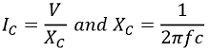
Therefore, on substituting,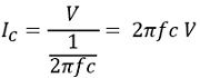
Suppose, the dielectric slab is of width b (in m) with area A (in m2) having permittivity ε (in farad/m), then its capacitance will be,![]()
Since,![]()
Substitute the value of IC,![]()
Also, putting, the value of C,![]()
The volume of dielectric slab = Area * width = A * b (in m3)![]()
Thus, the power loss per unit volume will be,![]()
Since, ε = ε0 . εr
ε0 = relative permittivity of the dielectric material = 1/36π * 10-9![]()
For the width of dielectric in cm,![]()
On simplifying,![]()
For a capacitor, with small loss angles,
Power factor, (p.f) = tan δ = loss tangent
Therefore,![]()
The loss factor of dielectric = εr (p.f)![]()
Thus, from this equation, we can say that the power loss per unit volume of dielectric is directly proportional to
- the operating frequency,
- the square of voltage gradient and
- the loss factor of the material.
Advantages
- It is inexpensive.
- Unlike other electric heating techniques, it offers uniform heating.
- Dielectric heating provides the good heating ability to non-conducting materials like plastics.
- It takes moderate time for heating.
- Heat controllability is easy.
- The heat produced depends on the applied frequency.
- A fast-heating process causing an efficient rise in temperature by eliminating temperature difference within the non-conducting material.
Disadvantages
- Its efficiency is only 50%, which is considered as its major drawback.
- Only the materials possessing high dielectric losses can be heated up.
- Sometimes radio interference exists because of high-frequency input.
Applications of Dielectric Heating
The various applications of dielectric heating are as follows:
- Food processing: In the field of food processing, it is used for various applications such as concentrating liquids within bottles, food cooking without outer shell removal, defrosting, dehydrating, germicidal heating, etc.
- Preheating of plastic preforms: It is one of the significant applications of dielectric heating as no other method can perform this in a uniform manner. The raw plastic material in the form of biscuits or tablets are called plastic preform and to convert a bulk of these biscuits or tablets into a specific shape they are kept inside the required mould.
Basically, to get them in desired shape uniform heating up to a certain level is required before putting them in the mould. - Sterilization: This process suits sterilizing medical equipment and aiding items like bandages, cotton, scissors, and other gauge instruments.
- Diathermy: To generate a specific body temperature in order to cure certain kinds of pains or diseases, body tissues and bones are subjected to dielectric heating.
- Electronic Sewing: It is the process by which the plastic sheets of umbrellas, raincoats, medicine containers can be sealed or joined. The materials with plastic films are not joined by ordinary stitching thus by the application of heat, sealing is provided to the material under the presence of mechanical pressure.
This is all about dielectric heating.
Leave a Reply