Both encoder and decoder are combinational logic circuits, however, one of the crucial difference between encoder and decoder is that an encoder provides binary code as its output. On the contrary, a decoder accepts binary code as its input.
An encoder is a device that converts the active data signal into a coded message format. However, a decoder performs inverse operation of the encoder and thus converts the coded input into original data input.
In order to have secured data transmission, encoders and decoders are employed in a communication system. The encoder and decoder perform encoding and decoding of data at transmitting and receiving end respectively.
Content: Encoder Vs Decoder
Comparison Chart
| Parameter | Encoder | Decoder |
|---|---|---|
| Input applied | Active input signal (original message signal) | Coded binary input |
| Output generated | Coded binary output | Active output signal (original message) |
| Input lines | 2n | n |
| Output lines | n | 2n |
| Opearation | Simple | Complex |
| Basic logic element | OR gate | AND gate along with NOT gate |
| Applications | E-mail , video encoders etc. | Microprocessors, memory chips etc. |
Definition of Encoder
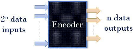
It is a combinational circuit that is used to convert the input signal in the form of coded output (digital data stream). An encoder consists of ‘2n’ number of input lines but has only ‘n’ output lines. When an input signal is applied to an encoder then logic circuitry involved within it converts that particular input into coded binary output.
The figure below shows the basic structure of an encoder:
Let us move further and have a look at 4 to 2 binary encoder that is shown below:
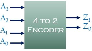
As we can see the four inputs provided to the encoder are A0, A1, A2, A3 and the 2 outputs are given as Z0 and Z1. It is noteworthy here that to have the particular binary code at the output of the encoder, out of the 4 inputs, only one of them can be high, for a given time.
Hence the truth table given below is for 4 to 2 binary encoder
| Input | Output | ||||
|---|---|---|---|---|---|
| A3 | A2 | A1 | A0 | Z1 | Z0 |
| 0 | 0 | 0 | 1 | 0 | 0 |
| 0 | 0 | 1 | 0 | 0 | 1 |
| 0 | 1 | 0 | 0 | 1 | 0 |
| 1 | 0 | 0 | 0 | 1 | 1 |
As we have already mentioned in the previous paragraph, that among all four, only one input will be 1 at a given time. This we can see in the truth table shown above.
Thus, the Boolean function for each output is given as
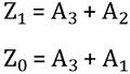
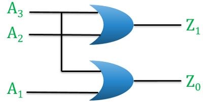
The figure below shows OR gate realization of a 4 to 2 binary encoder
Despite its advantage of providing the coded output, an encoder sometimes proves as a disadvantageous circuit and results in incorrect code, when 2 or more than 2 inputs are active high.
Definition of Decoder
A decoder is also a combinational circuit as encoder but its operation is exactly reverse as that of the encoder. A decoder is a device that generates the original signal as output from the coded input signal. It basically decodes the coded bits into another format.
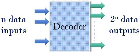
A decoder converts n bit coded data inputs into 2n output lines. The particular coded data is converted into original information signal with the help of internal logic circuitry involved within the decoder.
Let’s have a look at the basic decoder circuit:
Now, we will discuss 2 to 4 binary decoder in order to have a better understanding of decoders
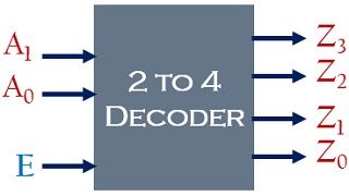
Here, the applied inputs to the circuit are A0 and A1 that provides 4 outputs namely Z0, Z1, Z2, Z3 and E shows the enable signal of the decoder.
Thus we will have the truth table for 2 to 4 decoder as shown below:
| Enable | Input | Output | ||||
|---|---|---|---|---|---|---|
| E | A1 | A0 | Z3 | Z2 | Z1 | Z0 |
| 0 | - | - | 0 | 0 | 0 | 0 |
| 1 | 0 | 0 | 0 | 0 | 0 | 1 |
| 1 | 0 | 1 | 0 | 0 | 1 | 0 |
| 1 | 1 | 0 | 0 | 1 | 0 | 0 |
| 1 | 1 | 1 | 1 | 0 | 0 | 0 |
Here, as we can see in the first row of the truth table that the enable terminal is low, thus no any input is fed to the device. Resultantly, which provide no result at the output. Hence, each combination of input will provide us high output when E will be high.
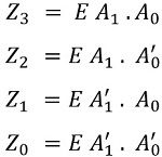
Hence the Boolean function for each output is given as:
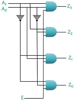
Let’s have a look at the AND gate realization of the decoder using NOT gate
Key Differences Between Encoder and Decoder
- The encoder circuit basically converts the applied information signal into a coded digital bit stream. While a decoder performs reverse operation and recovers the original information signal from the coded bits.
- The applied input in case of an encoder is an active input signal. As against decoder accepts coded binary data as its input.
- The encoder generates coded data bits as its output that is fed to the decoder. On the contrary, a decoder provides an active output signal (original message signal) in response to the coded data bits.
- The number of inputs accepted by an encoder is 2n but decoder accepts only n inputs.
- The output lines for an encoder is n while for the decoder it is 2n.
- The operation of an encoder is quite simple but the operation of the decoder is complex as it needs to understand the coding format of the encoder.
- In a communication system, the encoder is installed at the transmitting end whereas decoder circuit is installed at the receiving side.
Conclusion
As we are aware of the fact that both are combinational circuits but the operation of the two is exactly reverse of each other. One performs encoding of the original information signal, while the other decodes the coded data bits in order to have the exact message signal.
vishehsh kumar says
Nice article
Altaj Virani says
Please upload difference between MUX and Encoder like this….. I’m having my final exams from this 14th🙏🙏🙏🙏
sangwi kudakwashe says
good explanation.. I liked it