Definition: Surge Protector is a resistor which is inserted between rectifier circuit and the filter circuit to prevent the circuit from surge current. In general applications it may be omitted but in case of power supply it is beneficial to use surge protector or surge resistor.
You may be thinking that why we have introduced a new term here i.e. Surge Current. As we have not used this term in our previous articles.
So, surge current is the peak current which flows during initial charging process.
Consider a situation where the power supply is off from a long time. In this state the capacitor is uncharged. When the power supply switches from OFF state to ON state, the capacitor acts as short circuit. Thus, the initial charging current may be high. This sudden high current is called Surge Current.
Significance of Surge Protector
The initial high charging current may lead to destruction of circuit due to overheating of circuit elements. The current is high because there is no resistance in the path of current. The only resistance to surge current is the bulk resistance of diode and the resistance of transformer windings.
Thus, if we want to protect the circuit from getting damaged we need to use diodes which has high current ratings and which can withstand high peak voltages. The another alternative to protect the circuit from surge current is to use low capacity capacitor.
If the the capacity of the capacitor is below 1000 μF then the effect of surge current is low. On the other hand if the capacity of the capacitor is more than 1000 μF then the effect of surge current becomes quite dominating.
The reason behind the above mentioned fact is when the low capacity capacitor is used. The charging process will be completed in a very short duration of time. Thus, if the charging duration is small then the surge current will flow for a small period of time. While if we will use a capacitor of large capacity the charging duration will be more. Therefore, surge current will flow for a longer duration.
So far we have discussed the ways through which surge current can be minimized or its effect can be minimized. The ways we have discussed are either to use high current ratings diodes or to use small capacitor i.e. capacitor of small capacity. But what if we are working on a application which needs large capacitor like in power supplies. And what if we don’t have adequate high ratings diode then in such cases we need surge protector.
Surge Protector in Circuit
Surge protector is connected between the rectifier circuit and the capacitor filter circuit, so that during initial charging when high current is flowing through the circuit components it minimizes its effect. It provides impedance during excessive current flow.
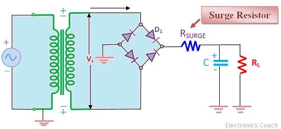
Its working can be understood by the below circuit diagram. In this a step down transformer is used with the bridge rectifier circuit. The step down transformer lowers the value of supply voltage for its processing. Then, the rectifier circuit converts into pulsating DC.
In the output section a filter circuit is used to regulate the output DC voltage. In addition to this a surge resistor is used between the filter and bridge rectifier circuit. It will lower the value of surge current flowing in the circuit.
Applications of Surge Resistor
It is mostly used in power supplies in which we need large capacitors of high capacity. This decreases the value of surge current flowing in the circuit up to a minimum and safe value. It is not used frequently but in special cases which require large capacity capacitors surge protector plays a vital role.
Leave a Reply