The load-commutated choppers are the ones that use the principle of load commutation. Through load commutation, a thyristor in conducting state is driven into a non-conducting state by making the load current zero according to the nature of the load circuit parameters.
It is one of the commutated chopper circuits other than voltage and current commutated chopper circuits.
Introduction
We know that choppers are known to be switches that are designed to perform turn-on and turn-off operations. In general, the representation of a chopper is such that there is a switch within a dotted rectangular box. Chopper basically changes fixed dc voltage into an adjustable dc voltage.
The process commutation is related to bringing the conducting thyristor to its non-conducting state. More simply, we can say, commutating a device is basically regarded as turning it off.
The technique of load commutation is based on the fact that a conducting thyristor can be turned off in one way if the load current becomes 0 due to the nature possessed by load circuit parameters while the other way is transferring the current flowing through the conducting thyristor to another device.
Circuit of Load-Commutated Chopper
The figure given below shows the circuit representation of load-commutated chopper:
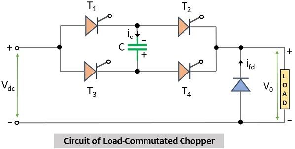
In the above figure, it is clearly represented that there are 4 thyristors in the given configuration namely, T1, T2, T3, and T4. Along with these, there is also a commutating capacitor represented by C and a freewheeling diode FD connected across the load over which the whole operation takes place.
Out of the four SCRs in the circuit, a pair i.e., two conduct at the same time while the other two will remain in the non-conducting state. Here for this particular arrangement thyristors T1 and T4 work as a pair and conduct simultaneously while thyristors T2 and T3 behave as another pair and allow current to flow through them simultaneously when the first pair is in a non-conducting state.
Working of Load-Commutated Chopper
Let us now proceed to understand how the whole circuit operation takes place.
Similar to the operating characteristics of the other two types of commutated choppers discussed earlier i.e., voltage commutated-chopper and current-commutated chopper, here also the operation begins by initially charging the capacitor with the value which is the peak of the applied voltage. However, here the upper plate of the capacitor is at negative polarity while the lower plate is having a positive polarity.
The necessary assumptions applied here are as follows:
- The current through the load is constant.
- The thyristors and diodes in the circuit behave as ideal switches.
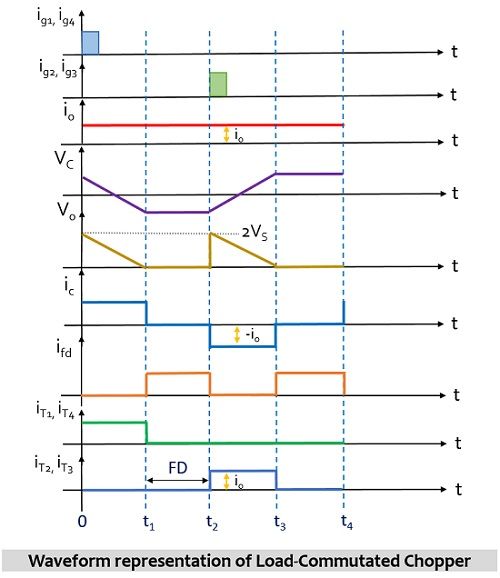
Once the capacitor C in the circuit gets charged with the supplied input then the chopper comes into the operating state. At time instant t = 0, a pair of thyristors consisting of T1 and T4 is triggered and current begins to flow through the path consisting Vdc – T1 – C – T4 and finally passes through the load. The direction of flow of current is shown below:
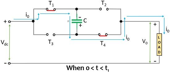
However, in this case, the voltage across the load will be the sum of input dc voltage supplied at the input and the voltage existing across the capacitor i.e., Vc. Hence, we will have
V0 = Vdc + VC = 2VC
The flow of load current through the capacitor linearly charges the capacitor C from Vdc to –Vdc in between the time instant t = 0 to t = t1. The moment at which the voltage across the capacitor reaches the value – Vdc, the voltage across the load will be
V0 = Vdc – Vdc = 0
This means the load voltage will get reduced from 2Vdc to 0 at instant t1.
It is to be noted here that when T1 and T4 are triggered then the other two thyristors in the circuit i.e., T2 and T3 are in reverse biased condition due to the voltage polarity across the capacitor. Thus, we can say at t = 0, VT3 = VT4 = – Vdc.
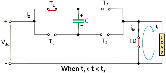
Furthermore, at instant t = t1, the capacitor gets slightly overcharged and this leads to forward bias the freewheeling diode present in the circuit. Once FD gets forward biased then the load current begins to flow through the freewheeling diode from instant t1 onwards. During the time instant t2 – t1 i.e., before reaching t2 and after instant t1, VC = – Vdc, V0 = 0, ic = 0, iT1= iT2 = 0 while the thyristor T2 and T3 will be in forward biased state thus, VT3 = VT4 = – Vdc. However, as the capacitor is overcharged by voltage ΔVdc therefore, VT1 = VT2 = – ΔVdc.
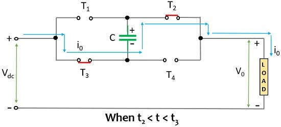
Till this time, triggering pulse has not been provided to thyristors T3 and T4 but at instant t2, a gate pulse is provided to T3 and T4 that again causes the load voltage to reach V0 = Vdc + VC = 2Vdc. This time the polarity across the capacitor reverse biases the thyristors T1 and T4 thereby leading to turning them off at instant t = t2. Hence, the load current will flow through Vdc – T3 – C – T2 leading to linearly charging the capacitor from –Vdc at t2 to Vdc at t3 and finally passing through the load. At this time, the flowing current leads to cause linear charging of the capacitor from –Vdc at t2 to Vdc at t3. By this time the load voltage falls from 2Vdc to 0.
At t3, again overcharging of the capacitor takes place and this forward biases the freewheeling diode and this leads to cause the flow of load current to take place through the loop where the freewheeling diode is present after instant t3.
Advantages
- Through this technique, any amount of load current can be commutated.
- The circuit works on the least filtering requirements thus support high-frequency operation in the range of kHz.
- The absence of an inductor in the circuit makes the circuit inexpensive and less noisy.
Disadvantages
- It exhibits low efficiency when dealing with high power applications as at high frequency, switching losses are higher.
- The capacitor in the circuit carries the full load current at a frequency of half the chopping frequency.
- The peak load voltage is double the supply voltage. In order to reduce this peak filtering can be done.
- The operation is successful only when one pair of SCRs is turned on while the other is turned off. The capacitor current of the circuit is of alternating nature thus, can be used for sensing.
This is all about the circuit operation of the load-commutated chopper.
Leave a Reply