Parallel operation of thyristors deals with the requirement of parallelly connecting multiple thyristors, the operation of SCRs in a parallel configuration and the factors to be considered when multiple thyristors are to be included.
Need for parallel connection of SCR
We have already discussed while discussing the series operation of thyristor that presently available thyristor ratings are 10 kV and 3 kA for voltage and current respectively. But sometimes even such high values of individual thyristor unable to fit for the high current and voltage rating of the circuit. This implies that in some applications there is a requirement of a high current or voltage rating than the one which is offered by a single thyristor.
The requirement of high voltage for a circuit than the rated value of a single thyristor is obtained by series connection of thyristor which we have discussed in the previous content.
The need for the parallel connection of the thyristor occurs whenever the load of the circuit requires more current than the rated current value of a single thyristor (SCR). More simply, we can say that a parallel connection is required when a load of a circuit requires a current greater than the rated value of the current of a single thyristor. This means to share the large value of load current, various SCRs are connected in a parallel configuration.
Hence, to achieve the higher value of current than the actual rated value of a single thyristor, various SCRs are connected parallelly forming a string.
Similar to the series connection of the thyristor, here also to ensure that overall current is getting equally shared between the SCRs present in the string, their respective I-V characteristics must be identical during forward conduction mode. Thus, in the configuration same category of thyristors must be connected.
String efficiency is a crucial parameter in reference to the parallel connection of SCR and is defined as:![]()
It is the measure of effective utilization of SCRs connected in the parallel configuration and is generally less than 1. The reason for its value less than unity is that although the SCRs in the configuration belong to the same class still there exist some dissimilarities amongst them relative to ratings and specifications which leads to unequal sharing of current amongst the parallelly connected SCR. As an outcome of which the string efficiency can never be equal to 1.
Now, the question arises, why the same class of SCRs shows the difference in characteristics thereby resultantly providing unequal current sharing.
So, basically in the configuration, the device that possesses a lower value of dynamic resistance shares a greater value of current. The temperature of that particular SCR will be comparatively more than the other having higher dynamic resistance. The increase in temperature leads to a further reduction in dynamic resistance thereby increasing the current more. This cumulative process occurs till the time the device gets damaged.
Similar to this, factors like difference in turning on time, delay time, finger voltage, etc. cause difficulty in the operation of the device. Though various SCRs in this configuration are parallelly added, they must possess a similar value of latching current i.e., must get turned on at the same time as well as must remain in the off state even after the removal of the gate pulse. Also, their holding currents must not show much variation that with the reduction in load current one of the parallelly connected devices in the string gets turned off when the current falls below its respective holding current value.
However, once the device gets turned off then, even when the current is increased then also the non-conducting device will not get on till the time gate pulse is not applied.
Operation of Parallelly connected SCR
Till now we have got the basic idea that when the current requirement of the circuit becomes more than the current rating offered by a single thyristor then thyristors are connected in parallel configuration. For the overall current to get equally shared between the SCRs they must possess similar I-V characteristics.
The figure below represents the parallel connection of two thyristors whose voltage drop VT must be the same so that the two can share an equal amount of current.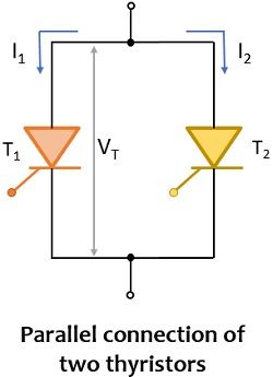
Have a look at the forward conduction characteristics of the SCRs with voltage drop VT.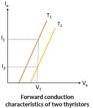
Here it is clear from the figure that SCR1 shares its rated current value I1 whereas SCR2 carries current I2 whose value is quite less than I1. The rated current of the circuit is 2I1 but the overall current which the unit will carry is I1 + I2.
Hence, in this case, the string efficiency will be given as:![]()
It is to be noted here that for proper operation of the SCRs we have to maintain the same temperature for which a common heat sink is required at the time of mounting.
Now, let us understand how can we achieve uniform current sharing. In order to maintain constant current across each parallelly connected SCR, a suitable value of external resistances must be connected across each SCR in series.
The figure shown below clearly represents the same: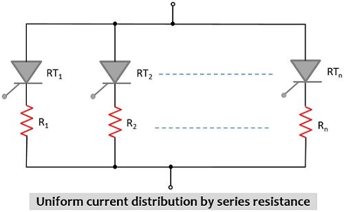
It is to be noted here that R1, R2, —- Rn corresponds to the external resistances while RT1, RT2, — RTn are the dynamic resistances of the various SCRs present in the configuration. To equalize the current flowing through each thyristor, the value of external resistances i.e., R1, R2, —-, Rn are selected in a way that RT1 + R1 = RT2 + R2 = —–RTn + Rn.
Sometimes there is an unequal distribution of current amongst the parallelly connected SCRs due to the inductive effect offered by the conductors which carry current in the given configuration. Basically, when the SCRs are arranged in an unsymmetrical manner like the one shown below: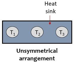
Then in this case in comparison to the two conductors present at the two ends, the centre one will have more inductance as it will have flux linkage from the other two conductors as well. Due to this reason, a comparatively less value of current will flow through the SCR which is present at the centre than the outer two. In order to overcome this problem, the SCRs are arranged symmetrically on the heat sink as shown below: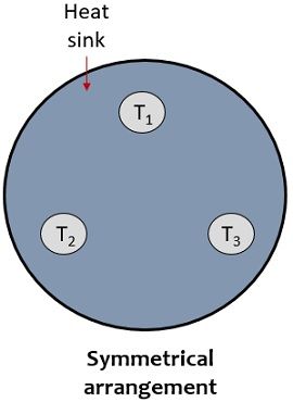
When we deal with ac circuits then the current distribution can be equalized by the use of reactors that offers magnetic coupling of the parallel path as indicated below: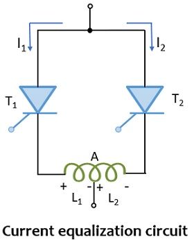
Here the reactor has a mid-point A, so for anode current I1 + I2, the flux generated in the two halves of the reactor will oppose each other. However, this opposing flux will get canceled due to which the voltage drop at the reactor will be 0.
In the case when I1 > I2 then the overall flux linkage will not be 0 despite the linked flux will induce emf L1 and L2 across the two halves of the reactor. The induced emf L1 will oppose the flow of current I1 and L2 will support the flow of current I2. In this way, buck and boost of I1 and I2 take place respectively and this helps in minimization of the unbalancing of current in the parallel configuration.
Leave a Reply