The series operation of thyristor explains why the serial connection of multiple thyristors is required, how the thyristors operate when serially connected and how can we deal with the drawbacks associated with the circuits that include multiple thyristors.
Need for series connection of SCR
After the introduction of SCR in 1957, the proposed rating of the thyristors has shown considerable improvement in recent years. At present, the thyristors are available with voltage and current ratings of 10 kV and 3 kA respectively. Despite offering such a high rating, in some applications, the required circuit rating is more than the rating offered by an individual thyristor.
This can be said in a way that, for some industrial applications, the voltage, and current ratings demand is comparatively higher than the rating which is offered by a single SCR. So, to deliver the requirement of the circuits for such applications serial connection of SCR is required.
Now the question arises when the serial and parallel connection of SCRs is made.
The serial connection of SCRs is made to fulfill the high voltage requirement of the circuit. So, when the voltage rating of the complete circuit surpasses the rating of a single thyristor then a number of SCRs are connected serially so that forward and reverse voltage can be shared. In the series connection, thyristors of the same class get connected serially.
It is to be noted here that the rating of all the SCRs, that are forming connections within the circuit are to be properly utilized as only after that the system will provide satisfactory operation.
There are two crucial terminologies that are said in reference to the connection of multiple SCRs in a circuit. These two are string efficiency and derating factor. The string is used to denote the connection of various SCRs.
String efficiency determines how effectively the SCRs in the string have been utilized. Note here that string efficiency for series and parallel connection of SCRs is defined in the same way. However, here we are providing the string efficiency of SCRs connected in series and it is given by:![]()
When the number of SCRs is more then the string will be more reliable.
Practically, string efficiency < 1
In order to get the highest achievable value of string efficiency, the SCRs that form a connection to generate string must possess identical I-V characteristics. However, thyristors of the same ratings do not offer identical characteristics which will lead to unequal sharing of voltage amongst the SCRs in the string. Due to this reason, string efficiency is not equal to unity. But to reduce the chances of unequal voltage sharing by the thyristors connected serially in a string one must use external equalizing circuits. Even the presence of equalizing circuit keeps the value of string efficiency less than 1.
Another term is derating factor, abbreviated as DRF, and determines how reliable the complete string is. It is given as:![]()
Operation of Serially Connected SCR
To achieve satisfactory serial operation of thyristors, firing to all the thyristors must be provided at the same instant of time. The voltage sharing of the thyristors is greatly influenced when there is a difference of few microseconds in the gate where triggering pulse is provided.
We have already discussed that the SCRs in series within a string should exhibit similar I-V characteristics. However, due to respective inherent variations of the SCRs, each of them might show variation in the voltage shared by them.
To understand this, suppose we have two SCRs T1 and T2 connected serially, with forward breakover voltages as VBO1 and VBO2.
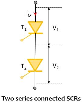
The leakage resistance of two SCRs will be given as V1/I0 for T1 and V2/I0 for T2, here leakage resistance of T1 is more than that of T2. As here the leakage current I0 is the same for both the SCRs, V1 is the rated voltage of T1 which is greater than the rated voltage of T2 i.e., V2. So, the thyristor with more leakage resistance will share a large part of the applied input voltage. Hence, it is said that the change in forward and reverse blocking characteristics of the thyristors possessing identical ratings leads to unequal distribution of voltage in the steady-state.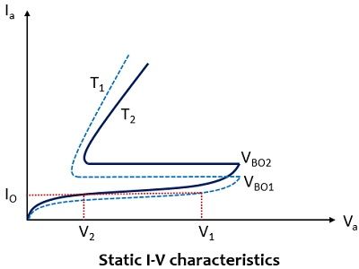
Here, it is clear that the two SCRs support voltage V1+V2 rather than 2V1. The string efficiency, in this case, will be given as:![]()
This can be clearly said that each SCR in the series configuration does not share the same voltage thus string efficiency is less than 1.
Now the question is – how this unequal voltage distribution can be equalized under steady-state?
So, to have an equal amount of voltage distribution, the resistance across each SCR in the string must be connected in a parallel configuration in such a way that each parallel combination must have a similar value of resistance. However, achieving this is a quite tough task, as in this case, a different value of resistance is required by each SCR. So, to simplify this, a more practical approach is connecting resistances R of equal value across each SCR in the configuration.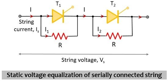
This shunt resistance connection in the series configuration is known as a static equalizing circuit.
Recently we have discussed the steady-state condition however, voltage distribution amongst the serially connected SCRs is not equal during transient conditions of turn-on, turn-off, and high-frequency operation. In such a case, it is said that the thyristor in the configuration, possessing the highest turn-on time will favor the full string voltage. To reduce the turn-on difference and so unequal voltage distribution, one way is to provide a high gate drive pulse with a fast rise time.
Consider the figure shown below to understand the unequal voltage distribution due to variation in reverse recovery characteristics of two SCRs.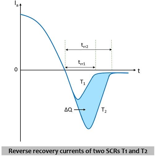
Here, it is shown that the reverse recovery time of T1 is less than T2, thus it gets recovered at a faster rate resultantly immediately limiting the reverse current. Due to this reason, more string voltage will be shared by T1 than T2. This shows that the voltage distribution will be unequal due to the difference in reverse recovery currents of the two SCRs.
While during turn-off conditions, the voltage distribution relies on the capacitance offered by the reverse-biased junctions of SCRs. Basically, each reverse-biased junction will offer different capacitances thereby offering unequal voltage distribution during turn-on and turn-off time. So, in such conditions, the use of shunt capacitances helps in voltage equalization.
More simply, the shunt capacitances across the thyristors compensate for the inequality in the self-capacitance of the thyristor. At the time of, turning off of the thyristor, the resultant of shunt capacitance and self-capacitance becomes equal.
Considering the blocking state of any of the SCR in series, it gets charged up to the voltage existing across it but it gets on, then the thyristor will discharge heavy current through itself. So, in order to limit the discharge current flowing through the SCR, the damping resistor denoted by RC is connected serially across each capacitor. This combination of C and RC is called a dynamic equalizing circuit. The arrangement is clearly shown below: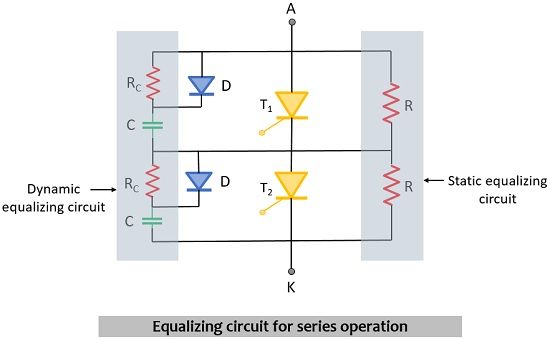
In the above circuit, the diode is present so as to provide a charging path to the capacitor at forward voltage conditions. However, the selection of diode is also crucial as it must possess soft recovery characteristics.
Leave a Reply