Definition: Potentiometer is an instrument that is used the determine the potential (voltage) between two points by performing a comparison with a known voltage. Basically, in order to do so, a manual variation in resistance is performed so as to control the current flow thereby determining the required voltage.
Potentiometers are normally abbreviated as POT and are nothing but variable resistors that measures the emf between two existing points.
The circuit of a potentiometer provides the exact value of emf. We know that voltmeters are also used to calculate the voltage in any circuit. Then, what is the advantage associated with a potentiometer that it is being used in the circuit to measure the potential difference?
A voltmeter is a device that provides an approximate value of the voltage across the circuit. But a potentiometer gives accurate or exact voltage value.
Now, how can we say that?
So, consider the circuit below, where a current of 2 A is flowing through a resistor of 5 ohms and a voltmeter is connected parallelly to determine the voltage through that circuit.
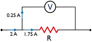
But the overall 2 A current will not flow through the resistor. As due to the parallel connection of the voltmeter and resistor, some current will flow through the voltmeter. This resultantly will decrease the actual voltage drop between the two points. Resultantly we will not get the exact value that was required to be calculated.
So, this is the reason for using a potentiometer to get the accurate potential difference instead of using a voltmeter.
Construction of Potentiometer
The figure below shows the circuit representation of a potentiometer: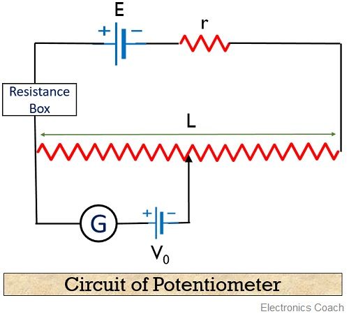
Here, an external power supply having known voltage E is connected in series with a resistance box whose value can be changed at any instant of time. Also, r is the internal resistance. A resistive wire of length L is taken which is made up of material like manganese and constantan.
The reason behind using these metals is that these hold a special property by virtue of which the resistance does not show much variation with the change in temperature. While in case of other metals, an abrupt change in the resistance of the metal is noticed with the variation in temperature.
So, one terminal of supply battery is connected with an end of the galvanometer by passing through the resistive wire while another terminal forms a direct connection with the resistive wire.
The galvanometer forms a connection through an unknown voltage to a middle point with the help of jockey. This jockey is used to perform the change in positions of the point. As this point is nothing but the acts as that second point in between which potential difference is to be measured.
So, let us proceed further to understand the working principle of potentiometers.
Working Principle of Potentiometer
Till now we have discussed the basic introduction of the potentiometer. Let us proceed further to determine the unknown voltage between two points.
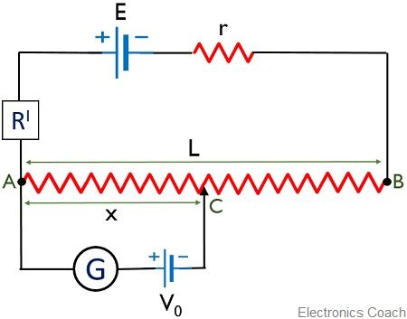
Consider the circuit below, where the jockey is connected to a point C in the resistive wire.
The resistance/ unit length of the resistive wire having length L is given as
ρ = R/L
So, the resistance of the resistive wire is given as
R = ρL
We know the current through the circuit is given as
V = IR
So, I = V/R
Thus the overall current will be given as
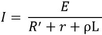
: R’ is the resistance chosen from the Resistance Box and r is the internal resistance.
I denote the overall current through the circuit.
Suppose, we have to calculate the voltage across point A and C having length x.
So, the voltage between point A and C will be given as
VAC = IRAC
Substituting the value of current in the above equation, we get
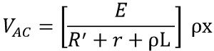
As the other values are constant except ρx.
So, we can say that the voltage between the two points is directly proportional to its length.
Hence,
VAC α x
VAC = σx
: σ denotes the proportionality constant
So, we can write
σ = VAC / x
It is known as the potential gradient.
Consider the figure below: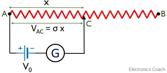
The figure shown above is nothing but the simplified form of the circuit shown at the beginning:
So, the net value of the voltage is given as
Net value = V0 – σx
This means the net value of the voltage across the circuit is the difference of voltage provided to the voltage between point A and C.
Case 1: When the jockey is at point A, then the length will be 0
So, the net value of the voltage will be V0
Since σx = 0
Case 2: When the length is increased by moving the jockey towards right,
So, at point C net value will be V0 – σx
This means with the increase in length the net value decreases.
Once the net value becomes 0, resulting in the deflection at the galvanometer to be 0.
Thus,
V0 = σx
Hence the potential difference across the two points can be calculated using the potentiometer.
Advantages of Potentiometer
- Low-cost instrument.
- It can be operated easily.
- Potentiometers are highly efficient and useful for measuring the large difference in potential between 2 points.
- It provides accurate results.
Disadvantages of Potentiometer
- Though the operation is quite simple but sometimes due to environmental effects the jockey creates problem while moving.
- External factors sometimes hinder the accuracy of producing the results.
This is all about potentiometer and its working principle.
Leave a Reply